
Concept explainers
Videos
(a)
Find the power dissipated by
(a)
Answer to Problem 41E
The power dissipated by
Explanation of Solution
Given Data:
The load resistance is
Formula used:
The expression for the power dissipated by load resistor is as follows.
Here,
Calculation:
The redrawn circuit diagram is given in Figure 1,
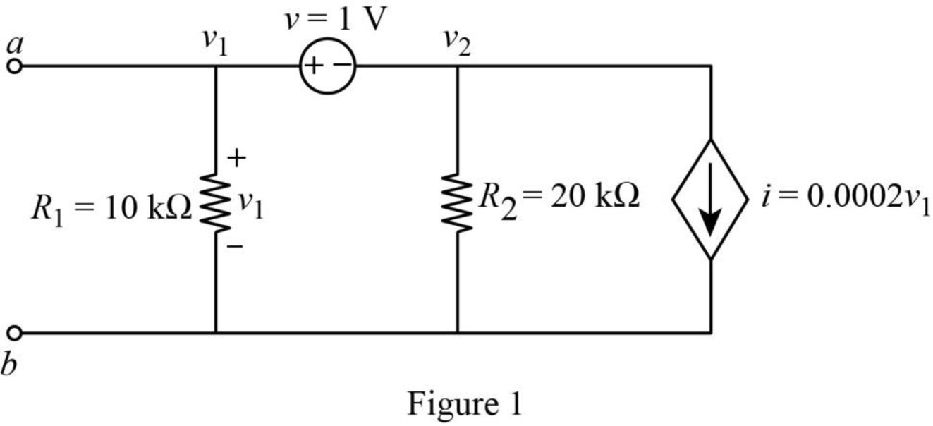
Refer to the redrawn Figure 1,
Apply Kirchhoff’s current law at node 1.
Here,
Substitute
Rearrange for
Rearrange for
Apply Kirchhoff’s voltage law between node 1 and 2.
Substitute
Rearrange for
So, the Thevenin voltage is
The redrawn circuit diagram is given in Figure 2,
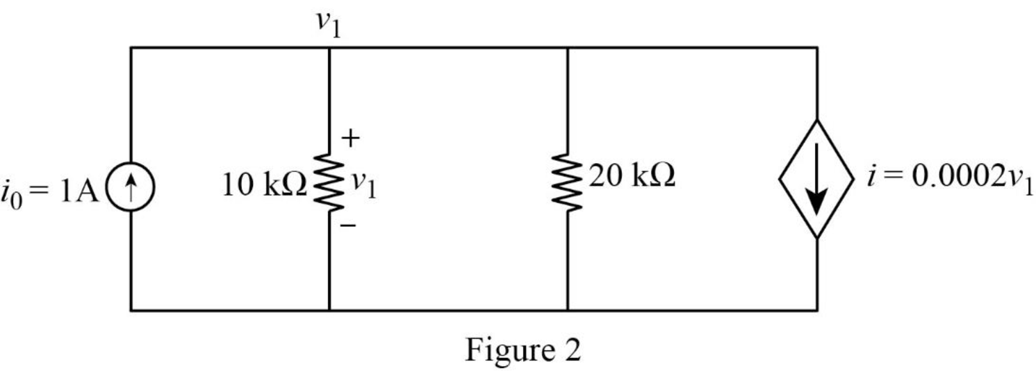
Refer to the redrawn Figure 2.
Apply Kirchhoff’s current law at node 1.
Here,
Substitute
Rearrange for
The expression for the Thevenin equivalent resistance is as follows,
Here,
Substitute
The redrawn circuit diagram is given in Figure 3,
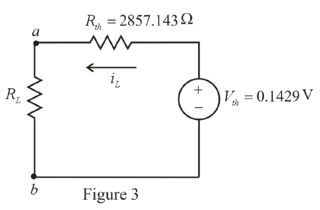
Refer to the redrawn Figure 3,
The expression for the current flowing in the circuit is as follows.
Here,
Substitute
Substitute
Conclusion:
Thus, the power dissipated by
(b)
The power dissipated by
(b)
Answer to Problem 41E
The power dissipated by
Explanation of Solution
Given Data:
The load resistance is
Calculation:
Refer to the redrawn Figure 3,
Substitute
Substitute
Conclusion:
Thus, the power dissipated by
(c)
The power dissipated by
(c)
Answer to Problem 41E
The power dissipated by
Explanation of Solution
Given Data:
The load resistance is
Calculation:
Refer to the redrawn Figure 3,
Substitute
Substitute
Conclusion:
Thus, the power dissipated by
Want to see more full solutions like this?
Chapter 5 Solutions
Loose Leaf for Engineering Circuit Analysis Format: Loose-leaf


- a. Design the circuit in Fig. 5.117 such that VR₂ = 3VR, and VR₂ 4 VR₂ b. If the current is reduced to 10 μA, what are the new val- ues of R₁, R₂, and R3? How do they compare to the re- sults of part (a)? AL- = إسكان E 10 mA 4₁₁ www www R₁ R₂ 64 V R3 wwwarrow_forwardFind the total resistance R, for each configuration in Fig. 5.86. Note that only standard resistor values were used. R R3 R3 R 0.39 kn 12 kn 1.20 2.7A RT R, (a) (b) R 82 kl 47A R 10kn R, {1 kn R4 Ry 1.8 n R.4, 820n R R, 12 kl 91 0 27 kn (c) (d) FIG. 5.86arrow_forwardConsider the circuit shown below. [5] Determine and sketch the Norton equivalent circuit and indicate all element values clearly. 5Ωarrow_forward
- Using the voltage divider rule or Kirchhoff's voltage law, determine the unknown voltages for the configurations in Fig. 5.119. Do not calculate the current! E₁ + • 50 V + wwwwww 3.3 ΚΩ + V = www 6.8 ΚΩ 4.7 ΚΩ 10 ΚΩ 30 V Ο + Vx E + 2 Ω 68 Ω 100 Ω Μ W www +1 + 1 + 1000 V | UNIVERSarrow_forwardFind the voltage across each resistor in Fig. 5.116 if R1 = 2R3 and R2 =7R3. E 60 V R₁ R₂ R3 www +51 +51 +5 IN UNIVERSITYarrow_forwardDetermine V in the circuit of Fig. 5. 100 V 16 Ω Μ 15Ω 35 Ω Fig. 5. 30 Ω 10 Ω Μ 1292 20 Ωarrow_forward
- For the series configuration in Fig . 5.98 constructed using standard value resistor without making a single calculation, which resistive element will have the most voltage across it? Which will have the least? which resistor will have the most impact on the total resistance and the the resulting current ? Find the total resistance and the current. Find the voltage across each element and review your response to part (a)arrow_forward5.40 Find the Norton equivalent of the circuit of Fig. 5-43. Reference I, up. Ans. 8 Ω.8Α 40 0 80 V 30 A 10 0 1000 V Fig. 5-43arrow_forwardExample: 5.1 Calculate the node voltages in the circuit shown in the below figure: 5 A 42 21 22 10 Aarrow_forward
- Current in a circuit is directly proportional to the resistance offered. Select one: O True O Falsearrow_forwardFind the voltage across each resistor in Fig. 5.123 if R1 = 2R3 and R2 = 7R3. E + 80 V R₁ R₂ R3 www +1+1+1arrow_forwardQuestion 41 With regard to the circuit of Fig. 5.82, determine the power dissipated by a) a 1 k resistor connected between a and b; b) a 4.7 k2 resistor connected between a and b; c) a 10.54 k resistor connected between a and b. ao bo 10 ΚΩ V₁ FIGURE 5.82 IV +- 20 ΚΩ 0.02v1arrow_forward
 Introductory Circuit Analysis (13th Edition)Electrical EngineeringISBN:9780133923605Author:Robert L. BoylestadPublisher:PEARSON
 Delmar's Standard Textbook Of ElectricityElectrical EngineeringISBN:9781337900348Author:Stephen L. HermanPublisher:Cengage Learning
 Programmable Logic ControllersElectrical EngineeringISBN:9780073373843Author:Frank D. PetruzellaPublisher:McGraw-Hill Education
 Fundamentals of Electric CircuitsElectrical EngineeringISBN:9780078028229Author:Charles K Alexander, Matthew SadikuPublisher:McGraw-Hill Education
 Electric Circuits. (11th Edition)Electrical EngineeringISBN:9780134746968Author:James W. Nilsson, Susan RiedelPublisher:PEARSON
 Engineering ElectromagneticsElectrical EngineeringISBN:9780078028151Author:Hayt, William H. (william Hart), Jr, BUCK, John A.Publisher:Mcgraw-hill Education,