
Loose Leaf for Engineering Circuit Analysis Format: Loose-leaf
9th Edition
ISBN: 9781259989452
Author: Hayt
Publisher: Mcgraw Hill Publishers
expand_more
expand_more
format_list_bulleted
Concept explainers
Videos
Textbook Question
Chapter 11, Problem 20E
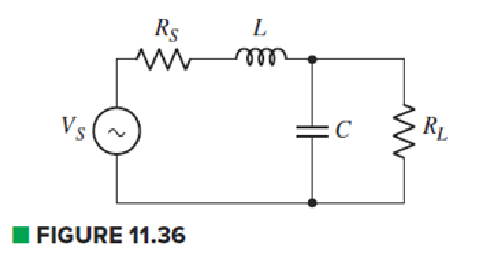
The circuit in Fig. 11.36 has a series resistance of Rs = 50 Ω and load resistance of RL = 82 Ω. If the impedance of the inductor is j40 Ω, what would be the required impedance of the capacitor to ensure maximum power transfer to RL?
Expert Solution & Answer
Want to see the full answer?
Check out a sample textbook solution
Students have asked these similar questions
A 2.5A current is flowing in a series circuit comprises of a coil with inductance 15mH
and resistance 102 and a variable capacitor. The supply voltage is 120V at 60 Hz.
Estimate the following:
i.
The capacitance and impedance.
ii.
Angle between supply voltage and current.
ii.
The reactive power consumed
QUESTION 1
A 1µF capacitor, a 150mH ideal inductor, and a 1.2k ohm resistor are connected in series with a function generator. Find the apparent power of the circuit if the supply voltage is 120V RMS 750HZ.
O 25.9 VA
O 8.75 VA
O 11.1 VA
O 1.55 VA
A capacitor and a resistor are connected in parallel to a 120-V, 60-Hz line. The resistor has a resistance of 40 Ω, and the capacitor has a capacitance of 132.6 µF. What is the total current flow through the circuit? What is the impedance of the circuit?What is the power factor of the circuit? How many degrees out of phase are the current and voltage?
Chapter 11 Solutions
Loose Leaf for Engineering Circuit Analysis Format: Loose-leaf
Ch. 11.1 - A current source of 12 cos 2000t A, a 200 ....Ch. 11.2 - Given the phasor voltage across an impedance ,...Ch. 11.2 - Prob. 3PCh. 11.2 - Prob. 4PCh. 11.2 - A voltage source vs is connected across a 4...Ch. 11.3 - If the 30 mH inductor of Example 11.7 is replaced...Ch. 11.4 - Calculate the effective value of each of the...Ch. 11.5 - For the circuit of Fig. 11.16, determine the power...Ch. 11.6 - Prob. 10PCh. 11 - Prob. 1E
Ch. 11 - Determine the power absorbed at t = 1.5 ms by each...Ch. 11 - Calculate the power absorbed at t = 0, t = 0+, and...Ch. 11 - Three elements are connected in parallel: a 1 k...Ch. 11 - Let is = 4u(t) A in the circuit of Fig. 11.28. (a)...Ch. 11 - Prob. 6ECh. 11 - Assuming no transients are present, calculate the...Ch. 11 - Prob. 8ECh. 11 - Prob. 9ECh. 11 - Prob. 10ECh. 11 - The phasor current I=915mA (corresponding to a...Ch. 11 - A phasor voltage V=10045V (the sinusoid operates...Ch. 11 - Prob. 13ECh. 11 - Prob. 14ECh. 11 - Find the average power for each element in the...Ch. 11 - (a) Calculate the average power absorbed by each...Ch. 11 - Prob. 17ECh. 11 - Prob. 18ECh. 11 - Prob. 19ECh. 11 - The circuit in Fig. 11.36 has a series resistance...Ch. 11 - Prob. 21ECh. 11 - Prob. 22ECh. 11 - Prob. 23ECh. 11 - Prob. 24ECh. 11 - Prob. 25ECh. 11 - Prob. 26ECh. 11 - Prob. 27ECh. 11 - Prob. 28ECh. 11 - Prob. 29ECh. 11 - Prob. 30ECh. 11 - Prob. 31ECh. 11 - Prob. 32ECh. 11 - Prob. 33ECh. 11 - (a) Calculate both the average and rms values of...Ch. 11 - Prob. 35ECh. 11 - FIGURE 11.43 Calculate the power factor of the...Ch. 11 - Prob. 37ECh. 11 - Prob. 38ECh. 11 - Prob. 40ECh. 11 - Prob. 41ECh. 11 - Prob. 42ECh. 11 - Prob. 43ECh. 11 - Compute the complex power S (in polar form) drawn...Ch. 11 - Calculate the apparent power, power factor, and...Ch. 11 - Prob. 46ECh. 11 - Prob. 48ECh. 11 - Prob. 49ECh. 11 - Prob. 50ECh. 11 - Prob. 51ECh. 11 - Prob. 52ECh. 11 - FIGURE 11.49 Instead of including a capacitor as...Ch. 11 - Prob. 54ECh. 11 - A load is drawing 10 A rms when connected to a...Ch. 11 - For the circuit of Fig. 11.50, assume the source...Ch. 11 - Prob. 57ECh. 11 - A source 45 sin 32t V is connected in series with...Ch. 11 - Prob. 60ECh. 11 - FIGURE 11.51 The circuit in Fig. 11.51 uses a Pi...Ch. 11 - Prob. 62ECh. 11 - Prob. 63ECh. 11 - You would like to maximize power transfer to a 50 ...
Knowledge Booster


Learn more about
Need a deep-dive on the concept behind this application? Look no further. Learn more about this topic, electrical-engineering and related others by exploring similar questions and additional content below.Similar questions
- The circuit is connected to a 60-Hz line. The apparent power in the circuit is 29.985 VA, and the power factor is 62.5%. The resistor has a voltage drop of 14.993 V, the inductor has an inductive reactance of 60 , and the capacitor has a capacitive reactance of 45 . ETITZVA29.985PF62.5%ER14.993VIRRPELILXL60VARsLLECICXC45VARsCCarrow_forwardYou are an electrician working in an industrial plant. A 30-hp three-phase induction motor has a current draw of 36 amperes at full load. The motor is connected to a 480-volt line. A three-phase wattmeter indicates a true power of 22 kW. Determine the power factor of the motor and the amount of capacitance needed to correct the power factor to 95. Also determine the minimum voltage rating of the capacitors. The capacitors are to be connected in wye.arrow_forwardInductive Circuits Fill in all the missing values. Refer to the following formulas: XL=2fLL=XL2ff=XL2L Inductance (H) Frequency (Hz) Inductive Reactance ( ) 1.2 60 0.085 213.628 1000 4712.389 0.65 600 3.6 678.584 25 411.459 0.5 60 0.85 6408.849 20 201.062 0.45 400 4.8 2412.743 1000 40.841arrow_forward
- A 15-F AC capacitor is connected in series with a 50 resistor. The capacitor has a voltage rating of 600 WVDC. The capacitor and resistor are connected to a 480-V, 60-Hz circuit. Is the voltage rating of the capacitor sufficient for this connection?arrow_forwardThree capacitors having capacitance values of 20F,40F, and 50F are connected in parallel to a 60 - Hz power line. An ammeter indicates a circuit current of 8.6 amperes. How much current is flowing through the 40F capacitor?arrow_forwardelem LI 4) A generator with fixed Vmax of 8V and an adjustable frequency of oscillation is connected to resistance R = 10092, inductances L₁ = 1.70 mH and L₂ = 2.30 mH, and capacitances C₁ = 4.00 mF, C₂ = 2.50 mF, and C3 = 3.50 mF. a) What frequency would give the largest current? b) What is the rms current when the generator is set a frequency of 3500 Hz? L₂ ele Rarrow_forward
- Determine the equivalent inductance of the inductive network with coupled coils shown in Figure. 2H le 3H 6 H 3H 4 H 5Harrow_forwardAn R−L−C series circuit has a current which lags the applied voltage by 45°. The voltageacross the inductance has a maximum value equal to twice the maximum value of voltageacross the capacitor. Voltage across the inductance is 300 sin(1000?) and R = 20 ohms. Computethe following: Value of total Impedance (Z) Value of Inductance (L) Value of Capacitance (C)arrow_forwardAn inductive impedance of 40 + j40 ohms is connected in parallel with a pure capacitor. What must be the reactance of the capacitor in ohms so that the total current is in phase with the supply voltage of 230V?arrow_forward
- An impedance coil is connected in series with a capacitor across a 220 V, 60 Hz acsupply. The circuit is designed such that the voltage across the impedance coil and thecapacitor are numerically equal. If this circuit operates at 0.866025403 leading powerfactor, determine the apparent power of the coil when the circuit current is 1 A. please answer asaparrow_forwardTwo inductances L1 and L2 are connected in parallel with mutual inductance M. The inductance in coil 1 is 6 mH and inductance in coil 2 is 9 mH. If the total inductance in parallel aiding is 2.143 mH, calculate the mutual inductance in parallel opposingarrow_forwardYou are working in an industrial plant. A bank of capacitors is to be used to correct the power factor of a 480-V, three-phase motor. The capacitor bank is connected in a wye. Each of the three capacitors is rated at 25 µF and 600 VDC. You have been told to reconnect these capacitors in delta. Can these capacitors be changed from wye to delta without harm to the capacitors?arrow_forward
arrow_back_ios
SEE MORE QUESTIONS
arrow_forward_ios
Recommended textbooks for you
 Delmar's Standard Textbook Of ElectricityElectrical EngineeringISBN:9781337900348Author:Stephen L. HermanPublisher:Cengage Learning
Delmar's Standard Textbook Of Electricity
Electrical Engineering
ISBN:9781337900348
Author:Stephen L. Herman
Publisher:Cengage Learning
Capacitors Explained - The basics how capacitors work working principle; Author: The Engineering Mindset;https://www.youtube.com/watch?v=X4EUwTwZ110;License: Standard YouTube License, CC-BY