
Videos
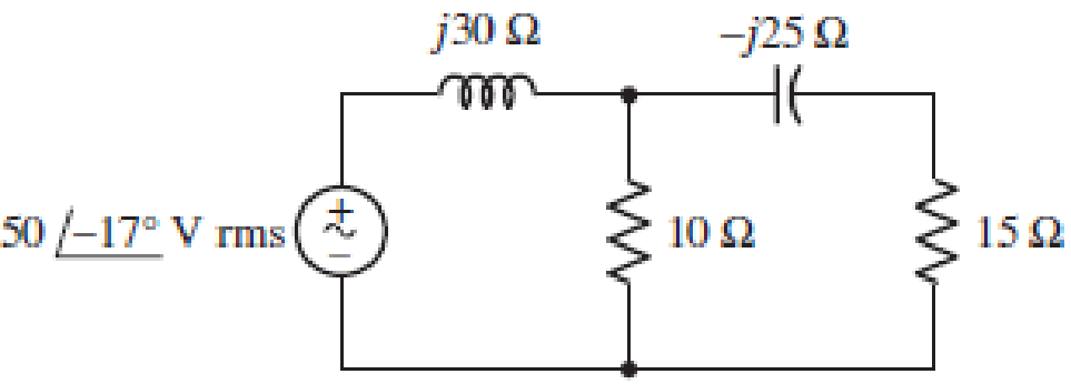
■ FIGURE 11.49
Instead of including a capacitor as indicated in Fig. 11.49, the circuit is erroneously constructed using two identical inductors, each having an impedance of j30 W at the operating frequency of 50 Hz. (a) Compute the complex power delivered to each passive component. (b) Verify your solution by calculating the complex power supplied by the source. (c) At what power factor is the source operating?
(a)
Find the complex power delivered to each passive element when
Answer to Problem 53E
The complex power delivered to
Explanation of Solution
Given data:
Refer to Figure 11.49 in the textbook for the given circuit.
Operating frequency is 50 Hz.
Formula used:
Write the expression for complex power delivered to the element as follows:
Here,
Write the expression for current in terms of voltage and impedance as follows:
Calculation:
Consider
Use the expression in Equation (2) and find the source current as follows:
Substitute
Use voltage division rule and find the voltage across
Substitute
Modify the expression in Equation (1) for the complex power delivered to
Substitute
Consider the node voltage across the shunt branches as
Substitute
Use current division rule and find the current through
Substitute
Modify the expression in Equation (1) for the complex power delivered to the
Substitute
Use voltage division rule and find the voltage across
Substitute
Use current division rule and find the current through
Substitute
Modify the expression in Equation (1) for the complex power delivered to the
Substitute
Use voltage division rule and find the voltage across
Substitute
Modify the expression in Equation (1) for the complex power delivered to the
Substitute
Conclusion:
Thus, the complex power delivered to
(b)
Verify the solution obtained in Part (a) by calculating the complex power supplied by the source.
Explanation of Solution
Calculation:
Modify the expression in Equation (1) for the complex power supplied by the source as follows:
Substitute
Write the expression for sum of complex delivered to (or absorbed by) each passive element as follows:
From Part (a), substitute
From the calculation, it is clear that, the complex power supplied by the source is equal to the complex power delivered to each passive element.
Conclusion:
Thus, the solution obtained in Part (a) is verified.
(c)
Find the power factor of the source.
Answer to Problem 53E
The power factor of the source is 0.253 lagging.
Explanation of Solution
Formula used:
Write the expression for complex power in the rectangular form as follows:
Here,
Write the expression for power factor as follows:
Calculation:
Rewrite the expression for complex power supplied by the source in rectangular form as follows:
Compare the complex power supplied by the source with the expression in Equation (3) and write the average and reactive power supplied by the source as follows:
Substitute 19.1482 W for
If the imaginary part of the complex power (reactive power) is positive value, then the load has lagging power factor. If the imaginary part is negative value, then the load has leading power factor.
As the imaginary part of the given complex power is positive value, the power factor is lagging power factor.
Conclusion:
Thus, the power factor of the source is 0.253 lagging.
Want to see more full solutions like this?
Chapter 11 Solutions
Loose Leaf for Engineering Circuit Analysis Format: Loose-leaf


- 5. A 240-V rms 60-Hz source supplies a parallel combination of a 5-kW heater and a 30-kVA induction motor whose power factor is 0.82. Determine: (a) the system apparent power (b) the system reactive power (c) the kVA rating of a capacitor required to adjust the system power factor to 0.9 lagging (d) the value of the capacitor required.arrow_forwardQUESTION 6 A motor with 15mH of inductance and an unknown internal resistance is connected to a 50V RMS 1.1kHz source. The power factor has been corrected by adding a 7231F capacitor in parallel with the motor. Determine the value of the internal resistance. (This is a trial and error question using the given answers for practice) O 100 O 1000 O 200 O 20arrow_forwarda) Write down the expression of instantaneous voltage for an AC voltage having a Peak value of 220 Volts and a frequency of 50 Hz provided at time t=0, the instantaneous voltage is 220 Volts. What is the instantaneous voltage of the source at time “t = 5 seconds” What is its RMS voltage? b) Two 200Ω resistances are connected in series with one 0.5 H Inductance and two 100μF Capacitance with the power supply of part (a). (i)Draw the circuit diagram of the above network (ii)What is the total impedance of the circuit (iii)What is the max current that flows through the Inductance? (iv)What is the max current that flows through each of the Capacitance? (v)What is the power dissipated in the circuit (vi)What is the power factor of the circuit (vii)What is the resonance frequency of the circuit? (viii) What is the maximum power dissipated by the circuit when it is in resonancearrow_forward
- 1. With a neat sketch briefly explain how an alternating voltage is produced when a coil is rotated in a magneticfield. 2. Derive expressions for average value and RMS value of a sinusoidally varying AC voltage 3. A circuit having a resistance of 12Ω, an inductance of 0.15 H and a capacitance of 100μf in series is connectedacross a 100V, 50Hz supply. Calculate the impedance, current, the phase difference between the current andsupply voltage. 4. Two circuits with impedances of Z1 = 10 + j15Ω and Z2 = 6 – j8Ω are connected in parallel. If the supply current is 20A, what is the power dissipated in each branch?arrow_forwardA coil of inductance 159.2mH and resistance 20ohms is connected in series with a 60ohms resistor to a 240V, 50HZ supply. Determine a) the impedance of the circuit, b) the current in the circuit, c) the circuit phase angle, d) the p.d. difference across the resistor and the coil, e) draw the circuit phasor diagram showing all voltages.arrow_forwardAn impedance coil having a resistance of 15 ohms and an inductance of 0.08 henryis connected in series with a variable capacitor. If a 117 volt 60 cps source isconnected to the circuit, what will be the capacitance of the capacitor and the current(a) when the circuit has a power factor of 0.866 leading and (b) when the voltagedrop across the coil is equal to the voltage drop across the capacitor?arrow_forward
- A capacitor drawing 4 kvar is placed in parallel with the electro-magnet that draws 3 kW of active power and 4 kvar of reactive power.. a. Calculate the new value of apparent power b. What is the new value of reactive power? c. What is the value of active power? d. What is the new power factor?arrow_forwardThe voltage represented by e = 240 Sin(377t) volts is connected across a 20 ohms resistor. The RMS current indicated by a modern DMM (digital multi-meter) is ... a) 24 A O b) 8.49 A O c) 12 A O d) 6 Aarrow_forwardGiven a series circuit comprised of the following element: 77.03-ohm resistor, practical inductor with internal resistance of 0.16 ohm and reactance of 74.36 ohms; and a capacitor with reactance of 12.45 ohms. Compute for the magnitude of its equivalent impedance in ohms. Note: Follow this reminder carefully. Compute to the nearest 4 decimal places. No Scientific notation. Do not round off in the middle of calculation. Use stored values.arrow_forward
- If a Marx generator is required to perform a 170 kV lightning impulse test, and you have capacitors rated at 60 kVdc available: (a) If the voltage efficiency is 90%, how many stages, n, should the Marx generator have, and what should the dc charging voltage, Vo, be? Using the output parameters to calculate the erected capacitance first, what should be the capacitance per stage if the minimum required stored energy for the test is 900 J? (b)arrow_forwardA coil has a resistance of 10 ohms and draws a current of 5A when connected across a 100-V, 60 Hz source. Determine A) the inductance in the coil, B) the power factor of the circuit and C) the reactive power. Answers: A) 45.94 mH, B) 0.5 lagging, C) 433 VARarrow_forwardA coil has 4ohms an inductance of 9.55mH.Deduce the following a)Draw a clear labelled circuit diagram. b) the reactive reactance c) the circuit impedance d) the current taken from a 240v,50vHz supply. e)Draw a phasor diagram f) The phase angle between the supply voltage and current.arrow_forward
 Introductory Circuit Analysis (13th Edition)Electrical EngineeringISBN:9780133923605Author:Robert L. BoylestadPublisher:PEARSON
 Delmar's Standard Textbook Of ElectricityElectrical EngineeringISBN:9781337900348Author:Stephen L. HermanPublisher:Cengage Learning
 Programmable Logic ControllersElectrical EngineeringISBN:9780073373843Author:Frank D. PetruzellaPublisher:McGraw-Hill Education
 Fundamentals of Electric CircuitsElectrical EngineeringISBN:9780078028229Author:Charles K Alexander, Matthew SadikuPublisher:McGraw-Hill Education
 Electric Circuits. (11th Edition)Electrical EngineeringISBN:9780134746968Author:James W. Nilsson, Susan RiedelPublisher:PEARSON
 Engineering ElectromagneticsElectrical EngineeringISBN:9780078028151Author:Hayt, William H. (william Hart), Jr, BUCK, John A.Publisher:Mcgraw-hill Education,