
Videos
Calculate the power absorbed at t = 0−, t = 0+, and t = 200 ms by each of the elements in the circuit of Fig. 11.27 if vs is equal to (a) −10u(−t) V; (b) 20 + 5u(t) V.
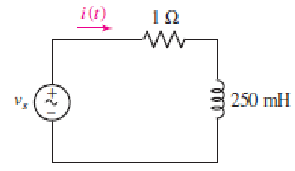
■ FIGURE 11.27
(a)
Find the power absorbed at
Answer to Problem 3E
The power absorbed at
The power absorbed at
The power absorbed at
Explanation of Solution
Given data:
Refer to Figure 11.27 in the textbook for the given circuit.
The circuit parameters are given as follows:
Formula used:
Write the expression for power absorbed by the voltage source as follows:
Here,
Write the expression for power absorbed by the resistor in the given circuit as follows:
Here,
Write the expression for conservation power in the circuit as follows:
Here,
Calculation:
Find the source voltage at
Write the expression for current through each element in the given circuit as follows:
Here,
Write the expression for time constant in the given circuit as follows:
Substitute
From the given circuit, the initial value of the current is determined as follows:
From the given data, substitute
Substitute
Find the current
Modify the expression in Equation (1) for
Substitute
Modify the expression in Equation (2) for
Substitute
Rewrite the expression in Equation (3) as follows:
Here,
Rewrite the expression in Equation (6) for the power absorbed by the inductor as follows:
Modify the expression for
Substitute
Find the source voltage at
Substitute
Modify the expression in Equation (1) for
Substitute 0 V for
Modify the expression in Equation (2) for
Substitute
Modify the expression in Equation (7) for
Substitute 0 W for
Find the source voltage at
Substitute
Modify the expression in Equation (1) for
Substitute 0 V for
Modify the expression in Equation (2) for
Substitute
Modify the expression in Equation (7) for
Substitute 0 W for
Conclusion:
Thus, the power absorbed at
The power absorbed at
The power absorbed at
(b)
Find the power absorbed at
Answer to Problem 3E
The power absorbed at
The power absorbed at
The power absorbed at
Explanation of Solution
Given data:
The source voltage is given as follows:
Calculation:
Find the source voltage at
Write the expression for current through each element in the given circuit as follows:
From Part (a), substitute 0.25 s for
Find the current
Modify the expression in Equation (1) for
Substitute 20 V for
Modify the expression in Equation (2) for
Substitute 20 A for
Substitute
Find the source voltage at
Substitute
Modify the expression in Equation (1) for
Substitute 25 V for
Modify the expression in Equation (2) for
Substitute 20 A for
Modify the expression in Equation (7) for
Substitute
Find the source voltage at
Substitute
Modify the expression in Equation (1) for
Substitute 25 V for
Modify the expression in Equation (2) for
Substitute 22.7533 A for
Modify the expression in Equation (7) for
Substitute
Conclusion:
Thus, the power absorbed at
The power absorbed at
The power absorbed at
Want to see more full solutions like this?
Chapter 11 Solutions
Loose Leaf for Engineering Circuit Analysis Format: Loose-leaf


- 11:23 ::! The figure shows the current through and the voltage across adevice. a) sketch the power delivered to the device for t>0. b) Find the total Energy absorbed by the device for the periodof 0arrow_forwardThe following circuit is composed of diodes and thyristors with an ideal behavior. Knowing that: Vs = 220 sin wt V, R = 10 kN, the firing angle of the thyristor T1 is equal to 20° and that T2 has the analog shot in the negative half-cycle of Vs, sketch the curves a) of the voltage for the thyristor T2 and b) for the load (purely resistive) T2 R 추D 추 Da losarrow_forward(a) The energy stored in 1200 turns inductor is 20 Joules. If the inductance value is 2 H, Find the following: (i) Current flowing through the coil. (ii) Flux linking with the coil in mwb. (iii) Average e.m.f. induced, if the current falls to zero in 100 msec. (b) Find equivalent inductance across A and B for the circuit shown below if L1 = 30 H and L2 =55H. L1 L2 A B Answers (a) Answer (b)arrow_forwardGiven a series circuit comprised of the following element: 81.59-ohm resistor, practical inductor with internal resistance of 0.99 ohm and reactance of 54.29 ohms; and a capacitor with reactance of 6.15 ohms. Compute for equivalent impedance angle in degrees. Note: Follow this reminder carefully. Compute to the nearest 4 decimal places. No Scientific notation. Do not round off in the middle of calculation. Use stored values. Write the numerical values only. No units in your final answer. Spaces are not allowed. Excessive number of decimals as compared to the required number of decimals may result to an incorrect answer.arrow_forwardA natural waterfalls, 50 meters high, constantly discharges 1.3m3 per second. A minihydroelectric plant is to be constructed at the bottom of the waterfalls. Calculate theelectric generator kW rating, assuming 90% mechanical to electrical conversion efficiencyand water turbine design efficiency of 70%.arrow_forwardConsider an RC series circuit with supplied voltage, Vs = 1 Vpeak (Figure C) If R = 10 K ohm, C = 1 mirco Farad, then what is the value of Time Constant, T? b. How long а. will it take the capacitor to get fully charged and discharged? c. List the equipments' name to construct and to analyze the RC series circuit? 10.0k2 С1 V1 1uF 1V 1kHz 0° Figure: Carrow_forwardDo we require three sets of individual 1 Ø Alternators in order to build a 3 Ø Alternator that is capable of producing 3 Ø electrical power output? Give a succinct explanation of your response using only one (1) sentence.arrow_forwardAn impedance coil is connected in series with a fixed resistor, and a 120-V, 50-cycle Source is then impressed across the combination. If the voltage drops across the coil and the fixed resistor are 70 and 80 V, respectively, when the circuit current is 1.4 A, calculate the resistance and inductance of the impedance coil.arrow_forwardRioad load BjoLoad Road (50 points) 网Load load source load source An electric dryer with an equivalent series resistance and inductance of values 9 N and 26 mH is plugged into a standard 240V(RMS) 60HZ wall socket. You may assume the phase of the source voltage is zero. a) Calculate the load current. 7. A help (numbers) I load !! In the time domain, A help (formulas) i toad (t) =arrow_forwardGiven a series circuit comprised of the following element: 77.03-ohm resistor, practical inductor with internal resistance of 0.16 ohm and reactance of 74.36 ohms; and a capacitor with reactance of 12.45 ohms. Compute for the magnitude of its equivalent impedance in ohms. Note: Follow this reminder carefully. Compute to the nearest 4 decimal places. No Scientific notation. Do not round off in the middle of calculation. Use stored values.arrow_forwardWhen a car has a dead battery, it can often be started by connecting the battery from another car across its terminals. The positive terminals are connected together as are the negative terminals. The connections in the circuit are shown in Figure. The current i is 30 A. Which car has the dead battery в 12V 12V O A O B O Both of them O Null 11:10 AM P Type here to search 耳。 a 40) ENG 4/8/2021 67 7 8 A9 Aarrow_forwardA resistor of 50 ohms, a 200mH inductor, and a 1.5 x 10⁻⁴ F capacitor are connected in parallel to a 120-volt, 60 cps source. Calculate: a) the total real, reactive, and apparent powers; b) power factor.arrow_forwardarrow_back_iosSEE MORE QUESTIONSarrow_forward_ios
 Introductory Circuit Analysis (13th Edition)Electrical EngineeringISBN:9780133923605Author:Robert L. BoylestadPublisher:PEARSON
 Delmar's Standard Textbook Of ElectricityElectrical EngineeringISBN:9781337900348Author:Stephen L. HermanPublisher:Cengage Learning
 Programmable Logic ControllersElectrical EngineeringISBN:9780073373843Author:Frank D. PetruzellaPublisher:McGraw-Hill Education
 Fundamentals of Electric CircuitsElectrical EngineeringISBN:9780078028229Author:Charles K Alexander, Matthew SadikuPublisher:McGraw-Hill Education
 Electric Circuits. (11th Edition)Electrical EngineeringISBN:9780134746968Author:James W. Nilsson, Susan RiedelPublisher:PEARSON
 Engineering ElectromagneticsElectrical EngineeringISBN:9780078028151Author:Hayt, William H. (william Hart), Jr, BUCK, John A.Publisher:Mcgraw-hill Education,