
Loose Leaf for Engineering Circuit Analysis Format: Loose-leaf
9th Edition
ISBN: 9781259989452
Author: Hayt
Publisher: Mcgraw Hill Publishers
expand_more
expand_more
format_list_bulleted
Videos
Textbook Question
Chapter 11, Problem 34E
(a) Calculate both the average and rms values of the waveform plotted in Fig. 11.42. (b) Verify your solutions with appropriate SPICE simulations. (Hint: You may want to employ two pulse waveforms added together.)
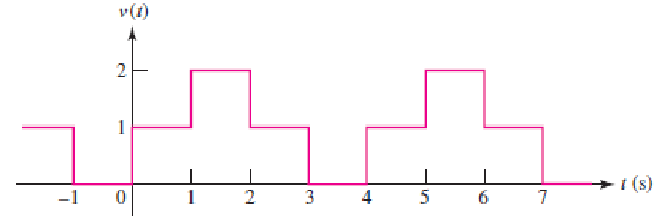
■ FIGURE 11.42
Expert Solution & Answer
Want to see the full answer?
Check out a sample textbook solution
Students have asked these similar questions
For the circuit of Fig.11.78 composed of standard values:
A. Determine the time constant.
B. Write the mathematical expression for the current It after the switch is closed
C. Repeat part (b) for VL and VR
D. Determine il and VL at one three- and five-time constants.
E. Sketch the waveforms of iL,VL and VR.
Assignment 2
This assignment is due on Tuesday 29/11/2021.
Q1
For the circuit shown in Figure 1, determine and sketch the input voltage V;, the current I, and the
output voltage Vo. The input voltage is sinusoidal with a peak value of 6V and a frequency of 40 Hz.
Via
+
2 kN
R2 10 kN Vo
Figure 1
EXAMPLE 11.7 Switch S, in Fig. 11.51 has been closed for a long
time. At 1 = 0 s, S, is opened at the same instant that S, is closed to avoid
an interruption in current through the coil.
a. Find the initial current through the coil. Pay particular attention to its
direction.
b. Find the mathematical expression for the current i, following the
closing of switch S,.
c. Sketch the waveform for i,.
486 ||| INDUCTORS
S
(t 0 s)
(1 = 0 s)
R2
8.2 k
I kN
12 mA R, = 2.2 k2
680 mH
E 6 V
o 000
Chapter 11 Solutions
Loose Leaf for Engineering Circuit Analysis Format: Loose-leaf
Ch. 11.1 - A current source of 12 cos 2000t A, a 200 ....Ch. 11.2 - Given the phasor voltage across an impedance ,...Ch. 11.2 - Prob. 3PCh. 11.2 - Prob. 4PCh. 11.2 - A voltage source vs is connected across a 4...Ch. 11.3 - If the 30 mH inductor of Example 11.7 is replaced...Ch. 11.4 - Calculate the effective value of each of the...Ch. 11.5 - For the circuit of Fig. 11.16, determine the power...Ch. 11.6 - Prob. 10PCh. 11 - Prob. 1E
Ch. 11 - Determine the power absorbed at t = 1.5 ms by each...Ch. 11 - Calculate the power absorbed at t = 0, t = 0+, and...Ch. 11 - Three elements are connected in parallel: a 1 k...Ch. 11 - Let is = 4u(t) A in the circuit of Fig. 11.28. (a)...Ch. 11 - Prob. 6ECh. 11 - Assuming no transients are present, calculate the...Ch. 11 - Prob. 8ECh. 11 - Prob. 9ECh. 11 - Prob. 10ECh. 11 - The phasor current I=915mA (corresponding to a...Ch. 11 - A phasor voltage V=10045V (the sinusoid operates...Ch. 11 - Prob. 13ECh. 11 - Prob. 14ECh. 11 - Find the average power for each element in the...Ch. 11 - (a) Calculate the average power absorbed by each...Ch. 11 - Prob. 17ECh. 11 - Prob. 18ECh. 11 - Prob. 19ECh. 11 - The circuit in Fig. 11.36 has a series resistance...Ch. 11 - Prob. 21ECh. 11 - Prob. 22ECh. 11 - Prob. 23ECh. 11 - Prob. 24ECh. 11 - Prob. 25ECh. 11 - Prob. 26ECh. 11 - Prob. 27ECh. 11 - Prob. 28ECh. 11 - Prob. 29ECh. 11 - Prob. 30ECh. 11 - Prob. 31ECh. 11 - Prob. 32ECh. 11 - Prob. 33ECh. 11 - (a) Calculate both the average and rms values of...Ch. 11 - Prob. 35ECh. 11 - FIGURE 11.43 Calculate the power factor of the...Ch. 11 - Prob. 37ECh. 11 - Prob. 38ECh. 11 - Prob. 40ECh. 11 - Prob. 41ECh. 11 - Prob. 42ECh. 11 - Prob. 43ECh. 11 - Compute the complex power S (in polar form) drawn...Ch. 11 - Calculate the apparent power, power factor, and...Ch. 11 - Prob. 46ECh. 11 - Prob. 48ECh. 11 - Prob. 49ECh. 11 - Prob. 50ECh. 11 - Prob. 51ECh. 11 - Prob. 52ECh. 11 - FIGURE 11.49 Instead of including a capacitor as...Ch. 11 - Prob. 54ECh. 11 - A load is drawing 10 A rms when connected to a...Ch. 11 - For the circuit of Fig. 11.50, assume the source...Ch. 11 - Prob. 57ECh. 11 - A source 45 sin 32t V is connected in series with...Ch. 11 - Prob. 60ECh. 11 - FIGURE 11.51 The circuit in Fig. 11.51 uses a Pi...Ch. 11 - Prob. 62ECh. 11 - Prob. 63ECh. 11 - You would like to maximize power transfer to a 50 ...
Knowledge Booster


Learn more about
Need a deep-dive on the concept behind this application? Look no further. Learn more about this topic, electrical-engineering and related others by exploring similar questions and additional content below.Similar questions
- The voltage in your home is 120 Vac effective (rms), what is the peak value? Voltage specified as 100 Vac is understood to be what value? rms, peak or peak-to-peak? Convert 280V peak-to-peak, to its rms value. Assume a sine wave. What peak-to-peak value of ac sine wave would do the same work as 50 Vdc? Oscilloscope can display which value? (peak or rms)arrow_forwardReferring to the Figure 2, compute the following values, given that the operating frequency is 60Hz and the voltage is 120V: (a) The inductive reactance (b) Source current (c) Apparent power, active power and reactive power Sketch and illustrate the power triangle with proper labelling, units and values. E 160 150 mH Figure 2arrow_forwardGiven a series circuit comprised of the following element: 81.59-ohm resistor, practical inductor with internal resistance of 0.99 ohm and reactance of 54.29 ohms; and a capacitor with reactance of 6.15 ohms. Compute for equivalent impedance angle in degrees. Note: Follow this reminder carefully. Compute to the nearest 4 decimal places. No Scientific notation. Do not round off in the middle of calculation. Use stored values. Write the numerical values only. No units in your final answer. Spaces are not allowed. Excessive number of decimals as compared to the required number of decimals may result to an incorrect answer.arrow_forward
- A 70-Vac source has the following waveform.Determine:a. the instantaneous voltage when t = 120 msb. the angle (1st occurrence) after t = 0 when the voltage is +80 Vc. the time (2nd occurrence) after t = 0 when the voltage is –10 Varrow_forwardA sinusoidal alternating voltage of effective value of 250 V and a frequency of 60 hz. It crosses the zero axis in a positive direction when t=0. Determine a) the instantaneous value of voltage after 12.45 msec; b) the time taken to reach 275 V after a period; c) the time to reach a value of 300 V after a passing through maximum positive value.arrow_forwardGiven a series circuit comprised of the following element: 88.01-ohm resistor, practical inductor with internal resistance of 0.76 ohm and reactance of 25.96 ohms; and a capacitor with reactance of 9.53 ohms. Compute for the magnitude of its equivalent impedance in ohms. Note: Follow this reminder carefully. Compute to the nearest 4 decimal places. No Scientific notation. Do not round off in the middle of calculation. Use stored values. Write the numerical values only. No units in your final answer. Spaces are not allowed. Excessive number of decimals as compared to the required number of decimals may result to an incorrect answerarrow_forward
- Q26 a). An alternating voltage is given by v=300 sin(400nt +0.55) volts. Find (i) Peak to Peak value (ii) r.m.s. value (ii) Average value (iv) Frequency (v) Time period (vi) Phase angle in degrees with respect to 300sin(400 Tt). Q26 b) A capacitor has a reactance of 60 ohms when operated on a 240 V, 50 Hz supply. Determine the value of capacitance in microfarad and also the current taken by the capacitor.arrow_forwardA 50-cycle voltage with maximum value of 24 V. (a) What will be the value of the instantaneous voltage at 0.00175 sec after the wave passesthrough in positive direction? (b) what will be the equation of the instantaneous current, if a non-inductive resistor of 9 ohms is connectedto the voltage source?arrow_forwardFig. 11.1 shows a circuit that switches on a warning lamp when the temperature in an oven falls below a set value. thermistor warning R. Fig. 11.1 Explain, with reference to the components in the circuit and point P, (i) why the warning lamp is on when the temperature in the oven is below the set value,arrow_forward
- The following figure indicates dc quantity. Inn. Rectangular pulse Select one: O True O Falsearrow_forwardA coil of wire having negligible resistance and inductance of 0.248 henries isconnected to a 117 – volt 50 – cycle source. Calculate (a) the inductive reactance,(b) the current, (c) the maximum power delivered to the inductor or returned to thesource, (d) the average power. Write equations for (e) the current and (f) the power. draw the circuit diagramarrow_forwardA voltage sine wave has an effective emf of 24 volts and angular velocity equal to 100π rad/s.(a) Determine the instantaneous voltage at t= 30ms(b) At what time(ms) will the instantaneous voltage be if v(t) = -20Volts after passing through the first negative peak voltage(c) At what time(ms) will the instantaneous voltage be if v(t) = Erms after completing one cycle. (d) Draw the waveformarrow_forward
arrow_back_ios
SEE MORE QUESTIONS
arrow_forward_ios
Recommended textbooks for you
 Introductory Circuit Analysis (13th Edition)Electrical EngineeringISBN:9780133923605Author:Robert L. BoylestadPublisher:PEARSON
 Delmar's Standard Textbook Of ElectricityElectrical EngineeringISBN:9781337900348Author:Stephen L. HermanPublisher:Cengage Learning
 Programmable Logic ControllersElectrical EngineeringISBN:9780073373843Author:Frank D. PetruzellaPublisher:McGraw-Hill Education
 Fundamentals of Electric CircuitsElectrical EngineeringISBN:9780078028229Author:Charles K Alexander, Matthew SadikuPublisher:McGraw-Hill Education
 Electric Circuits. (11th Edition)Electrical EngineeringISBN:9780134746968Author:James W. Nilsson, Susan RiedelPublisher:PEARSON
 Engineering ElectromagneticsElectrical EngineeringISBN:9780078028151Author:Hayt, William H. (william Hart), Jr, BUCK, John A.Publisher:Mcgraw-hill Education,
Introductory Circuit Analysis (13th Edition)
Electrical Engineering
ISBN:9780133923605
Author:Robert L. Boylestad
Publisher:PEARSON
Delmar's Standard Textbook Of Electricity
Electrical Engineering
ISBN:9781337900348
Author:Stephen L. Herman
Publisher:Cengage Learning
Programmable Logic Controllers
Electrical Engineering
ISBN:9780073373843
Author:Frank D. Petruzella
Publisher:McGraw-Hill Education
Fundamentals of Electric Circuits
Electrical Engineering
ISBN:9780078028229
Author:Charles K Alexander, Matthew Sadiku
Publisher:McGraw-Hill Education
Electric Circuits. (11th Edition)
Electrical Engineering
ISBN:9780134746968
Author:James W. Nilsson, Susan Riedel
Publisher:PEARSON
Engineering Electromagnetics
Electrical Engineering
ISBN:9780078028151
Author:Hayt, William H. (william Hart), Jr, BUCK, John A.
Publisher:Mcgraw-hill Education,
02 - Sinusoidal AC Voltage Sources in Circuits, Part 1; Author: Math and Science;https://www.youtube.com/watch?v=8zMiIHVMfaw;License: Standard Youtube License