
Concept explainers
Videos
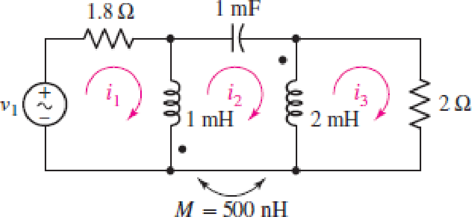
In the circuit of Fig. 13.43, M is reduced by an order of magnitude. Calculate i3 if v1 = 10 cos (800t − 20°) V.
FIGURE 13.43
Find the value of
Answer to Problem 15E
The value of
Explanation of Solution
Given data:
Refer to Figure 13.43 in the textbook for the given circuit.
The value of mutual inductance is reduced by an order of magnitude. Therefore, write the value of mutual inductance as follows:
Formula used:
Write the expression for reactance due to self-inductance as follows:
Here,
Write the expression for reactance due to capacitance as follows:
Here,
Write the expression for reactance due to mutual-inductance as follows:
Here,
Calculation:
From the given source voltage, write the value of angular frequency and the source voltage
Rewrite the expression for
Substitute
Substitute
Substitute
Substitute
Use the obtained values of reactance due to inductor and capacitors and draw the phasor representation for the given circuit as shown in Figure 1.
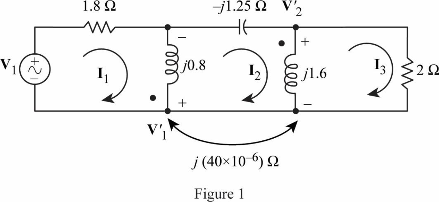
Apply KVL to the loop-
Neglect the dimensions and write the expression as follows:
Apply KVL to the loop-
Apply KVL to the loop-
Neglect the dimensions and write the expression as follows:
From the circuit in Figure 1, write the expression for
From the circuit in Figure 1, write the expression for
Rewrite the expression in Equation (4) as follows:
Substitute
Simplify the expression as follows:
Rearrange the expression in Equation (6) as follows:
Substitute
Simplify the expression as follows:
From Equation (9), substitute
Simplify the expression as follows:
Substitute
Simplify the expression as follows:
Rearrange the expression in Equation (5) as follows:
Substitute
From Equation (11), substitute
Simplify the expression as follows:
Substitute
Simplify the expression as follows;
Rewrite the expression in polar form to obtain the value of
Conclusion:
Thus, the value of
Want to see more full solutions like this?
Chapter 13 Solutions
Loose Leaf for Engineering Circuit Analysis Format: Loose-leaf


- Determine the phasor currents Ij and Iz in the circuit of Fig. 13.13. 50 j20 -w . 12/60° V j6n (I, Figure 13.13 For Practice Prob. 13.2. Answer: 2.15/86.56°, 3.23 /86.56° A.arrow_forwardA coil with an iron core absorbs a current of 0.5 A when a sinusoidal voltage of 220 V rms is applied to its terminals. If the power absorbed was 30 W, deduce the equivalent circuit of the coil. Ans: RFe = 1,617.64 Ω and Xμ = 457.38 Ω. (I need the procedure)arrow_forwardShort Problem: Given a parallel RLC circuit comprised of the following element: 63.92-ohm resistor, ideal inductor with reactance of 46.65 ohms; and a capacitor with reactance of 8.65 ohms. Compute for reactive power in VArs given an ac voltage source of 100 cis 0 volts. Give only the absolute value. Note: Follow this reminder carefully. Compute to the nearest 4 decimal places. No Scientific notation. Do not round off in the middle of calculation. Use stored values. Write the numerical values only. No units in your final answer. Spaces are not allowed. Excessive number of decimals as compared to the required number of decimals may result to an incorrect answer.arrow_forward
- R1 1000 V1 C1 =1pF 12Vpk ~1kHz 0° Find the capacitor's reactance Xc, impedance Z, the circuit's current, and peak voltage across the resistor. Xc: ohms, Round to the nearest whole number. Do not include units. Z: ohms: Round to the nearest whole number. Do not include units. Current: mA : round to the nearest milliamp. Do not include units. Vr: Vpk round to the nearest TENTH. (1 decimal place) Do not include units. Hiarrow_forwardGiven a parallel RLC circuit comprised of the following element: 72.06-ohm resistor, ideal inductor with reactance of 69.81 ohms; and a capacitor with reactance of 10.98 ohms. Compute for reactive power in VArs given an ac voltage source of 100 cis 0 volts. Give only the absolute value. PLEASE ANSWER WITHIN 30 MINUTES. Round off to the nearest 4 decimal places. No Scientific notation. Do not round off in the middle of calculation. Use stored values. Write the numerical values only. No units in your final answer. Spaces are not allowed.arrow_forward13. Given Ll 32s sin t;L (163 +1) a) d) tsint sint b) sin c) tsin 4arrow_forward
- 1.A coil when connected across 40 V DC draws 640 W. When connected across (104 + j78) V AC, the coil draws 1000 W. Solve for the coil’s resistance and reactance and the current passing through in rectangular form. 2.An impedance coil having a 0.2 lagging pf is connected in series with a 300 W lamp in order to supply the lamp with 120 volt from a 208 volt, 60 Hz source. What is the voltage across the terminals of the impedance coil?arrow_forwardQUESTION 58 Short Problem: Given a parallel RLC circuit comprised of the following element: 94.42-ohm resistor, ideal inductor with reactance of 60.84 ohms; and a capacitor with reactance of 15.03 ohms. Compute for reactive power in VArs given an ac voltage source of 100 cis 0 volts. Give only the absolute value. Note: Follow this reminder carefully. Compute to the nearest 4 decimal places. No Scientific notation. Do not round off in the middle of calculation. Use stored values. Write the numerical values only. No units in your final answer. Spaces are not allowed. Excessive number of decimals as compared to the required number of decimals may result to an incorrect answer.arrow_forwardFundamentals of Electrical Engineering 2020/2021 Dr. Yaseen H. Tahir xample: (example 15-3, page 388, David) (H. W.) A 1 MF capacitance is to be constructed from rolled-up sheets of aluminum foil separated by a layer of paper 0.1 mm thick. Calculate the required area for each sheet of foil if the relative permittivity of the paper is 6. Jution:arrow_forward
- Determine the phasor currents I, and I₂ in the circuit of Fig. 13.13. 5Ω j2 Ω 100 /60° V 4₁ j6 Ω I + -j4Ω j3 Ωarrow_forwardFigure 13.83 +v(V) 3. Determine the period and frequency of the sawtooth waveform of Fig. 13.85 20 16 26 36 I (ms) Figure 13.85arrow_forwardA coil has a reactance of 330 ohms in a circuit with a supply of frequency 16 kHz. Determine the inductance of the coil. Inductance in mH= For the circuit shown below, the maximum power supplied to the load resistor (Pmax) = 475 Watts and VTh = 180 V. RTh ww IL VTh R1 The value of Load resistance, R̟ is wwarrow_forward
 Introductory Circuit Analysis (13th Edition)Electrical EngineeringISBN:9780133923605Author:Robert L. BoylestadPublisher:PEARSON
 Delmar's Standard Textbook Of ElectricityElectrical EngineeringISBN:9781337900348Author:Stephen L. HermanPublisher:Cengage Learning
 Programmable Logic ControllersElectrical EngineeringISBN:9780073373843Author:Frank D. PetruzellaPublisher:McGraw-Hill Education
 Fundamentals of Electric CircuitsElectrical EngineeringISBN:9780078028229Author:Charles K Alexander, Matthew SadikuPublisher:McGraw-Hill Education
 Electric Circuits. (11th Edition)Electrical EngineeringISBN:9780134746968Author:James W. Nilsson, Susan RiedelPublisher:PEARSON
 Engineering ElectromagneticsElectrical EngineeringISBN:9780078028151Author:Hayt, William H. (william Hart), Jr, BUCK, John A.Publisher:Mcgraw-hill Education,