
Concept explainers
Videos
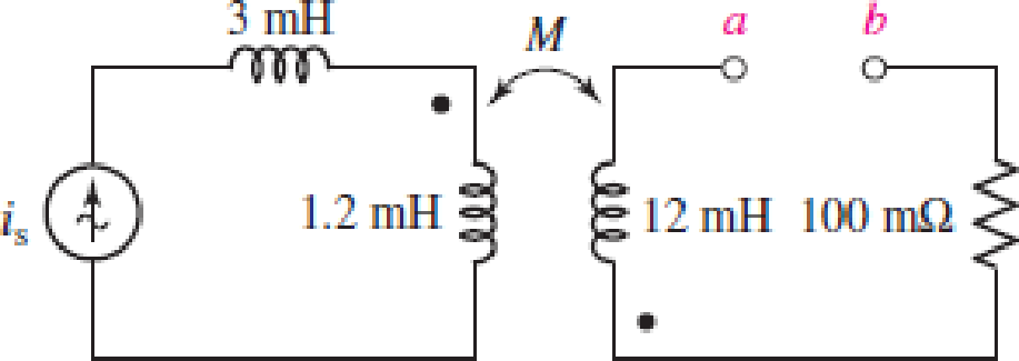
Consider the circuit represented in Fig. 13.53. The coupling coefficient k = 0.75. If is = 5 cos 200t mA, calculate the total energy stored at t = 0 and t = 5 ms if (a) a-b is open-circuited (as shown); (b) a-b is short-circuited.
FIGURE 13.53
(a)
Find the total energy stored in the system at
Answer to Problem 27E
The total energy stored in the system at
Explanation of Solution
Given data:
Refer to Figure 13.53 in the textbook for the given circuit.
The terminals a-b in the given circuit are open circuited.
Formula used:
Write the expression for energy stored in the magnetic field due to self-inductance of the coil at an instant of time as follows:
Here,
Calculation:
As the terminals a-b in the given circuit are open circuited, the current through the secondary winding loop is 0 A. Therefore, the total energy stored in the system is only due to the primary coils of the given circuit.
From the given circuit, find the value of inductance of primary coil when the terminals a-b in the given circuit are open circuited as follows:
Find the current through the primary coil at
Modify the expression in Equation (1) for energy stored in the system due to the coil
Substitute
Find the current through the primary coil at
Modify the expression in Equation (1) for energy stored in the system due to the coil
Substitute
Conclusion:
Thus, the total energy stored in the system at
(b)
Find the total energy stored in the system at
Answer to Problem 27E
The total energy stored in the system at
Explanation of Solution
Given data:
The terminals a-b in the given circuit are short-circuited.
Formula used:
Write the expression for energy stored in the magnetic field due to mutual inductance of the coils at an instant of time as follows:
Here,
Write the expression for mutual inductance in terms of self-inductance of primary and secondary coils as follows:
Here,
Calculation:
Substitute
From the given circuit, find the current
Substitute
Simplify the expression as follows:
Find the current through the secondary coil at
From Part (a), the energy stored in the system due to the coil
Modify the expression in Equation (1) for energy stored in the system due to the coil
Substitute
Rearrange the expression in Equation (2) to find the energy stored in the magnetic field due to the mutual inductance of the coils at
Substitute
Write the expression for total energy stored in the system at
Substitute
From Part (a), the energy stored in the system due to the coil
Find the current through the secondary coil at
Modify the expression in Equation (1) for energy stored in the system due to the coil
Substitute
Rearrange the expression in Equation (2) to find the energy stored in the magnetic field due to the mutual inductance of the coils at
Substitute
Modify the expression in Equation (4) for total energy stored in the system at
Substitute
Conclusion:
Thus, the total energy stored in the system at
Want to see more full solutions like this?
Chapter 13 Solutions
Loose Leaf for Engineering Circuit Analysis Format: Loose-leaf


- A coil having an inductance of 200 mH is magnetically coupled to another coil having an inductance of 500 mH. The coefficient of coupling between the coils is 0.65. Calculate the equivalent inductance if the coils are connected in parallel aiding HTML Editorarrow_forwardA coil in a 60-Hz circuit has a resistance of 100 N and an inductance of 0.45 H. Calculate (a) the coil's reactance and (b) the circuit's impedance. *Please make sure the full solution is viewable and does not cut off.arrow_forwardCourse: Electrical Engineering Subject: Electrical Apparatus Instructions: • Write the GIVEN with their respective symbols and units. • Do not skip the SOLUTIONS, do it step-by-step with their respective symbols and units • Round up to 3 three decimal places the FINAL ANSWERS and BOX it. Problem: Consider the following circuit. Determine the coupling coefficient. Calculate the energy stored in the coupled inductors at time t = 1.5 sec. 1 H 4Ω ww 40 cos 21 V 2 H 1 Harrow_forward
- What is the inductance L of the primary of a transformer whose input is 150V at 60 Hz and the current drawn is 3.5 Amps? Assume no current in the secondary.arrow_forwardAnswer the following: a. A capacitor is rated 100 kVAR, 380 V, 50 Hz. Find its rating at 60 Hz, 220 V. b. The resistance of a coil is measured to be 20 Ω. A 230 V, 60 Hz is impressed on the coil and the current taken is 3.2 A. Find the inductance of the coil.arrow_forwardA coil induces 350 mV when the current changes at the rate of 1 A/s. The value of inductance is (a) 3500 mH (b) 350 mH (c) 250 mH (d) 150 mHarrow_forward
- 2 A voltage e(t) = 100sin 314t is applied to a series circuit consisting of 10ohms resistance, 0.0318H inductance and a capacitor of 63.6uF. Calculate a)expression for i(t), b)phase angle between voltage and current, c) power factor and active power consumed, d) peak value of the pulsating energy, e) draw the diagrams and circuit.arrow_forwardA series L–R–C circuit has a supply input of 5 volts. Given that inductance, L = 5 mH, resistance, R = 75ohms and capacitance, C = 0.2µF, determine A) the value of the maximum voltage across the capacitor. B) A capacitor having a Q-factor of 250 is connected in series with a coil which has a Q-factor of 80. Calculate the overall Q-factor of the circuit.arrow_forwardA bridge rectifier is connected to a transformer which takes 230V 50Hz at its input, and supplies a loadof 200 Ω. If the turns ratio of the transformer is 4:1 what will be the output voltage (DC), the peakinverse voltage and the output frequency.arrow_forward
- The total inductance for the following three coupled coils is 13 10 12 9 Final exam -2nd Stage - Electri... × docs.google.com 11 m 7H 4 H 2 H 8 H 5 H m 10 H *arrow_forwardA 40µF, 600V paper capacitor is available but we need one having rating of about 300µF. It is proposed to use a transformer to modify the 40µF so that it appears as 300µF. The following transformer ratios are available: 120V/330V; 60V/450V; 480V/150V. Which transformer is the most appropriate and what is the reflected value of the 40µF capacitance? To which side of the transformer should the 40µF capacitor be connected?arrow_forwardThe following circuit is composed of diodes and thyristors with an ideal behavior. Knowing that: Vs = 220 sin wt V, R = 10 kN, the firing angle of the thyristor T1 is equal to 20° and that T2 has the analog shot in the negative half-cycle of Vs, sketch the curves a) of the voltage for the thyristor T2 and b) for the load (purely resistive) T2 R 추D 추 Da losarrow_forward
 Introductory Circuit Analysis (13th Edition)Electrical EngineeringISBN:9780133923605Author:Robert L. BoylestadPublisher:PEARSON
 Delmar's Standard Textbook Of ElectricityElectrical EngineeringISBN:9781337900348Author:Stephen L. HermanPublisher:Cengage Learning
 Programmable Logic ControllersElectrical EngineeringISBN:9780073373843Author:Frank D. PetruzellaPublisher:McGraw-Hill Education
 Fundamentals of Electric CircuitsElectrical EngineeringISBN:9780078028229Author:Charles K Alexander, Matthew SadikuPublisher:McGraw-Hill Education
 Electric Circuits. (11th Edition)Electrical EngineeringISBN:9780134746968Author:James W. Nilsson, Susan RiedelPublisher:PEARSON
 Engineering ElectromagneticsElectrical EngineeringISBN:9780078028151Author:Hayt, William H. (william Hart), Jr, BUCK, John A.Publisher:Mcgraw-hill Education,