
Loose Leaf for Engineering Circuit Analysis Format: Loose-leaf
9th Edition
ISBN: 9781259989452
Author: Hayt
Publisher: Mcgraw Hill Publishers
expand_more
expand_more
format_list_bulleted
Concept explainers
Videos
Textbook Question
Chapter 13, Problem 22E
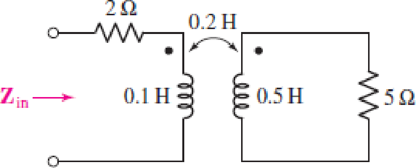
(a) Find Zin(jω) for the network of Fig 13.50. (b) Plot Zin over the frequency range of 0 ≤ ω ≤ 1000 rad/s. (c) Find Zin(jω) for ω = 50 rad/s.
FIGURE 13.50
Expert Solution & Answer
Want to see the full answer?
Check out a sample textbook solution
Students have asked these similar questions
13.42. Determine the angle and magnitude of
16( s + 1)
GH
s(s+ 2)(s+4)
at the following points in the s-plane: (a) s=j2, (b) s= - 2+ j2, (c) s= - 4 + j2. (d) s= -6.
(e) s= - 3.
13.43. Determine the angle and magnitude of
20( s + 10 + j10)(s + 10 – j10)
(s+ 10)(s+ 15)(s+ 25)
GH =
at the following points in the s-plane: (a) s=j10, (b) s=j20, (c) s= – 10 + j20, (d) s= - 20 + j20,
(e) s = - 15 + j5.
A series RLC circuit has a resistance of 25.0 Ω, a capacitance of 50.0 μF,
and an inductance of 0.300 H. If the circuit is driven by a 120 V, 60 Hz
source, calculate
i. the total impedance of the circuit.
ii. the rms current in the circuit.
iii. the phase angle between the voltage and the current.
iv. the resonance frequency of the circuit.
15. A series RLC circuit has elements R = 150 ohms, L = 18 mH and C=
2.22 microfarads. What is the equivalent impedance of the circuit if the frequency is
60 Hz?.
Chapter 13 Solutions
Loose Leaf for Engineering Circuit Analysis Format: Loose-leaf
Ch. 13.1 - Assuming M = 10 H, coil L2 is open-circuited, and...Ch. 13.1 - For the circuit of Fig. 13.9, write appropriate...Ch. 13.1 - For the circuit of Fig. 13.11, write an...Ch. 13.2 - Let is = 2 cos 10t A in the circuit of Fig. 13.14,...Ch. 13.3 - Element values for a certain linear transformer...Ch. 13.3 - (a) If the two networks shown in Fig. 13.20 are...Ch. 13.3 - If the networks in Fig. 13.23 are equivalent,...Ch. 13.4 - Prob. 8PCh. 13.4 - Let N1 = 1000 turns and N2 = 5000 turns in the...Ch. 13 - Prob. 1E
Ch. 13 - With respect to Fig. 13.36, assume L1 = 500 mH, L2...Ch. 13 - The circuit in Fig. 13.36 has a sinusoidal input...Ch. 13 - Prob. 4ECh. 13 - Prob. 5ECh. 13 - The circuit in Fig. 13.38 has a sinusoidal input...Ch. 13 - The physical construction of three pairs of...Ch. 13 - Prob. 8ECh. 13 - Prob. 9ECh. 13 - Calculate v1 and v2 if i1 = 5 sin 40t mA and i2 =...Ch. 13 - Prob. 11ECh. 13 - For the circuit of Fig. 13.41, calculate I1, I2,...Ch. 13 - Prob. 13ECh. 13 - Prob. 14ECh. 13 - In the circuit of Fig. 13.43, M is reduced by an...Ch. 13 - Prob. 16ECh. 13 - Prob. 17ECh. 13 - Prob. 18ECh. 13 - Prob. 19ECh. 13 - Note that there is no mutual coupling between the...Ch. 13 - Prob. 21ECh. 13 - (a) Find Zin(j) for the network of Fig 13.50. (b)...Ch. 13 - For the coupled coils of Fig. 13.51, L1 = L2 = 10...Ch. 13 - Prob. 24ECh. 13 - Prob. 25ECh. 13 - Prob. 26ECh. 13 - Consider the circuit represented in Fig. 13.53....Ch. 13 - Compute v1, v2, and the average power delivered to...Ch. 13 - Assume the following values for the circuit...Ch. 13 - Prob. 30ECh. 13 - Prob. 31ECh. 13 - Prob. 32ECh. 13 - Prob. 33ECh. 13 - Prob. 34ECh. 13 - Prob. 35ECh. 13 - Prob. 36ECh. 13 - Prob. 37ECh. 13 - FIGURE 13.60 For the circuit of Fig. 13.60, redraw...Ch. 13 - Prob. 39ECh. 13 - Prob. 40ECh. 13 - Calculate the average power delivered to the 400 m...Ch. 13 - Prob. 42ECh. 13 - Calculate the average power delivered to each...Ch. 13 - Prob. 44ECh. 13 - Prob. 45ECh. 13 - Prob. 46ECh. 13 - Prob. 47ECh. 13 - Prob. 48ECh. 13 - A transformer whose nameplate reads 2300/230 V, 25...Ch. 13 - Prob. 52ECh. 13 - As the lead singer in the local rock band, you...Ch. 13 - Obtain an expression for V2/Vs in the circuit of...Ch. 13 - Prob. 55E
Knowledge Booster


Learn more about
Need a deep-dive on the concept behind this application? Look no further. Learn more about this topic, electrical-engineering and related others by exploring similar questions and additional content below.Similar questions
- A circuit consists of an inductor which has a resistance of 10 Ω and an inductance of 0.3 H, in serieswith a capacitor of 30 μF capacitance. Calculate(a) the impedance of the circuit to currents of 40 Hz (b) the resonant frequency (c) the peakvalue of stored energy in joules when the applied voltage is 200 V at the resonant frequency.Answer: [58.31 Ω; 53 Hz; 120 J]arrow_forward5- In the circuit of Figure 5, draw the frequency domain equivalent of the circuit at O=1000 rad/sec and find voltage V1. 2 Cos iot E A 201F 502 3 5oles Clot+30) Figure 5arrow_forwardQ1/ For the below system, if you know that the input is (t) = A sin(wt) , explain and draw the relationship between the value of B and (the magnitude and the phase) of the output? R(s) 1 G(s) = C(s) (s +B)arrow_forward
- A coil has an impedance of (50 + j70) Ω. A capacitor is connected in parallel in order to produce resonance. If the source voltage is 120 V, find the power drawn by the circuit.arrow_forward1. The mathematical expression of the frequency spectrum of a general FM signal shows that it has technically a limited bandwidth a wide bandwidth an infinite bandwidth narrow bandwidth none of the choices 2. The break frequency for commercial FM broadcast of the preemphasis and deemphasis network is 2.122 kHz 2122 kHz 75 kHz 75 Hz none of the choicesarrow_forwardDetermine if each statement is True or False; if false, please explain whya) A forced oscillator is when a system is being yelled at to perform a specific motion.b) Impedance is a measure of the total resistance a RLC series circuit has towards current.c) The phase angle tells us how “out-of-phase” the charge on the capacitor iswith the driving voltage.arrow_forward
- Exercises 1. An impedance of R = 100 ohms and L 20mH is connected across another impedance of R = 150 ohms and C = 250microfarad. Determine at which frequency, this circuit will resonate across a variable AC frequency source of 240V. Determine also the Q factor of the coil used.arrow_forwardQ.5: a) Correct any five of the following sentences using suitable scientific phrases. 1. At any resonant circuit the input impedance is reactance (X or Xc). 2. The locus of inductive load is a vector in the 2nd quadrant. 3. Any non-sinusoidal wave can be represented by a sum of sine waves with harmonic frequencies. 4. The power dissipated in a resistance is equal to 21'R in non-sinusoidal input signal. 5. In transient circuit when the switch is closed for a long time the inductor behaves as an open circuit. 6. The DC input voltage could be represented by Vs in Laplace methods. 7. The electrical energy is stored in the resistance. (15 marks]arrow_forwardAn impedance of R=100 ohms and L=20 mH is connected across another impedance of R=150 ohms and C=250 microfarad. Determine at which frequency, this circuit will resonate across a variable AC frequency source of 240 V. Determine also the Q factor of the coil used.arrow_forward
- Reactive power must not be compensated to guarantee an efficient delivery of active power to loads. Select one: True Falsearrow_forwardA coil with R=5.2 Ohms and L=36.3 mH, is in parallel with a 2.91 mF capacitance. Calculate the impedance at resonance (in ohms)? (Use 2 decimal places. Unit is not required.)arrow_forwardWhat is the magnitude of the impedance Z between nodes A and B with a resistance of R, a capacitance of C, and an inductance of L with the following values: ω = 3900 rad/s, R = 50 Ω, L=2.0×10^−8 H, C = 12 μF.arrow_forward
arrow_back_ios
SEE MORE QUESTIONS
arrow_forward_ios
Recommended textbooks for you
 Introductory Circuit Analysis (13th Edition)Electrical EngineeringISBN:9780133923605Author:Robert L. BoylestadPublisher:PEARSON
 Delmar's Standard Textbook Of ElectricityElectrical EngineeringISBN:9781337900348Author:Stephen L. HermanPublisher:Cengage Learning
 Programmable Logic ControllersElectrical EngineeringISBN:9780073373843Author:Frank D. PetruzellaPublisher:McGraw-Hill Education
 Fundamentals of Electric CircuitsElectrical EngineeringISBN:9780078028229Author:Charles K Alexander, Matthew SadikuPublisher:McGraw-Hill Education
 Electric Circuits. (11th Edition)Electrical EngineeringISBN:9780134746968Author:James W. Nilsson, Susan RiedelPublisher:PEARSON
 Engineering ElectromagneticsElectrical EngineeringISBN:9780078028151Author:Hayt, William H. (william Hart), Jr, BUCK, John A.Publisher:Mcgraw-hill Education,
Introductory Circuit Analysis (13th Edition)
Electrical Engineering
ISBN:9780133923605
Author:Robert L. Boylestad
Publisher:PEARSON
Delmar's Standard Textbook Of Electricity
Electrical Engineering
ISBN:9781337900348
Author:Stephen L. Herman
Publisher:Cengage Learning
Programmable Logic Controllers
Electrical Engineering
ISBN:9780073373843
Author:Frank D. Petruzella
Publisher:McGraw-Hill Education
Fundamentals of Electric Circuits
Electrical Engineering
ISBN:9780078028229
Author:Charles K Alexander, Matthew Sadiku
Publisher:McGraw-Hill Education
Electric Circuits. (11th Edition)
Electrical Engineering
ISBN:9780134746968
Author:James W. Nilsson, Susan Riedel
Publisher:PEARSON
Engineering Electromagnetics
Electrical Engineering
ISBN:9780078028151
Author:Hayt, William H. (william Hart), Jr, BUCK, John A.
Publisher:Mcgraw-hill Education,
Series compensation of long transmission lines; Author: Georg Schett;https://www.youtube.com/watch?v=smOqSxFBvVU;License: Standard Youtube License