
Loose Leaf for Engineering Circuit Analysis Format: Loose-leaf
9th Edition
ISBN: 9781259989452
Author: Hayt
Publisher: Mcgraw Hill Publishers
expand_more
expand_more
format_list_bulleted
Concept explainers
Videos
Textbook Question
Chapter 13, Problem 23E
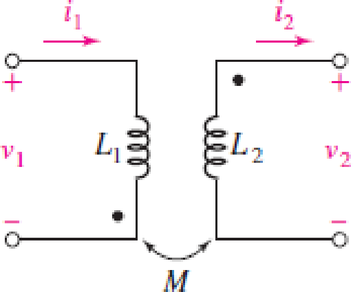
For the coupled coils of Fig. 13.51, L1 = L2 = 10 H, and M is equal to its maximum possible value. (a) Compute the coupling coefficient k. (b) Calculate the energy stored in the magnetic field linking the two coils at t = 200 ms if i1 = 10 cos 4t mA and i2 = 2 cos 4t mA.
FIGURE 13.51
Expert Solution & Answer
Want to see the full answer?
Check out a sample textbook solution
Students have asked these similar questions
11. Two coupled coils have self-inductances L1 = 2 H and L2 = 0.5 H, and a coefficient of coupling K = 0.9. Determine the turns ratio N1/N2 of the two coils.
2- When the frequency of the voltage across of a (50HZ) power transformer increased by 10% of
the rated value, the no-load current:
a) Increased.
b) Decreased.
c) Remains the same.
3- The self-inductance of an iron-cored coil is a function of:
a) The geometry of the coil only.
b) The current passing through it only.
c) The frequency of the applied voltage only.
d) All of the above factors.
kindly help me with this problem thank you so much!
Instructions: Evaluate and Show neat, logical, and complete solution.show final answers in four decimal places.
1. The primary coil of a power transformer has an inductance of 30 mH with negligible resistance. Find its inductive reactance at a frequency of 60 Hz and current it will draw a 120 V line.
Chapter 13 Solutions
Loose Leaf for Engineering Circuit Analysis Format: Loose-leaf
Ch. 13.1 - Assuming M = 10 H, coil L2 is open-circuited, and...Ch. 13.1 - For the circuit of Fig. 13.9, write appropriate...Ch. 13.1 - For the circuit of Fig. 13.11, write an...Ch. 13.2 - Let is = 2 cos 10t A in the circuit of Fig. 13.14,...Ch. 13.3 - Element values for a certain linear transformer...Ch. 13.3 - (a) If the two networks shown in Fig. 13.20 are...Ch. 13.3 - If the networks in Fig. 13.23 are equivalent,...Ch. 13.4 - Prob. 8PCh. 13.4 - Let N1 = 1000 turns and N2 = 5000 turns in the...Ch. 13 - Prob. 1E
Ch. 13 - With respect to Fig. 13.36, assume L1 = 500 mH, L2...Ch. 13 - The circuit in Fig. 13.36 has a sinusoidal input...Ch. 13 - Prob. 4ECh. 13 - Prob. 5ECh. 13 - The circuit in Fig. 13.38 has a sinusoidal input...Ch. 13 - The physical construction of three pairs of...Ch. 13 - Prob. 8ECh. 13 - Prob. 9ECh. 13 - Calculate v1 and v2 if i1 = 5 sin 40t mA and i2 =...Ch. 13 - Prob. 11ECh. 13 - For the circuit of Fig. 13.41, calculate I1, I2,...Ch. 13 - Prob. 13ECh. 13 - Prob. 14ECh. 13 - In the circuit of Fig. 13.43, M is reduced by an...Ch. 13 - Prob. 16ECh. 13 - Prob. 17ECh. 13 - Prob. 18ECh. 13 - Prob. 19ECh. 13 - Note that there is no mutual coupling between the...Ch. 13 - Prob. 21ECh. 13 - (a) Find Zin(j) for the network of Fig 13.50. (b)...Ch. 13 - For the coupled coils of Fig. 13.51, L1 = L2 = 10...Ch. 13 - Prob. 24ECh. 13 - Prob. 25ECh. 13 - Prob. 26ECh. 13 - Consider the circuit represented in Fig. 13.53....Ch. 13 - Compute v1, v2, and the average power delivered to...Ch. 13 - Assume the following values for the circuit...Ch. 13 - Prob. 30ECh. 13 - Prob. 31ECh. 13 - Prob. 32ECh. 13 - Prob. 33ECh. 13 - Prob. 34ECh. 13 - Prob. 35ECh. 13 - Prob. 36ECh. 13 - Prob. 37ECh. 13 - FIGURE 13.60 For the circuit of Fig. 13.60, redraw...Ch. 13 - Prob. 39ECh. 13 - Prob. 40ECh. 13 - Calculate the average power delivered to the 400 m...Ch. 13 - Prob. 42ECh. 13 - Calculate the average power delivered to each...Ch. 13 - Prob. 44ECh. 13 - Prob. 45ECh. 13 - Prob. 46ECh. 13 - Prob. 47ECh. 13 - Prob. 48ECh. 13 - A transformer whose nameplate reads 2300/230 V, 25...Ch. 13 - Prob. 52ECh. 13 - As the lead singer in the local rock band, you...Ch. 13 - Obtain an expression for V2/Vs in the circuit of...Ch. 13 - Prob. 55E
Knowledge Booster


Learn more about
Need a deep-dive on the concept behind this application? Look no further. Learn more about this topic, electrical-engineering and related others by exploring similar questions and additional content below.Similar questions
- Q1. The primary winding of a transformer carries a distorted current having the following components: Fundamental current: 520 A 3rd harmonic: 270 A 23rd harmonic: 47 A The winding has a dc resistance of 3 m2 and the stray losses are equal to 4% of the Joule effect losses. Calculate: (i) The effective value IT of the current (ii) The K factor (iii)The Joule effect losses in the primary winding (iv) The stray losses and the total losses in the primary winding (v) The component in IT that produces the largest Joule effect loss (vi) The component in IT that produces the largest stray lossarrow_forwardWhat is the impedance of a transformer coil that has 340' of #18 copper wire and an inductance of 70mH at 60Hz? 1000’ of #18 copper wire is 16 ohms.arrow_forward7. The no-load current of a transformer is 4A at 0.25 pf when supplied at 25V, 60Hz. Find the magnetizing component of the no-load currentarrow_forward
- A coil has resistance of 5 ohm and inductive reactance of 4 ohm. a) what is the impedance of the coil? b) what is the admittance of the coil?arrow_forwardAn ideal transformer has two secondary coils with number of turns 100 and 150respectively. Theprimary coil has 125 turns and supplied from 400 V, 50 Hz,single phase source. If the two secondarycoils are connected in series, the possible voltages across the series combination will be:(A) 833.5 V or 166.5 V (B) 833.5 V or 320 V (C) 320 V or 800 V (D) 800 V or 166.5 Varrow_forwardTwo identical 900 turn coils A and B lie in parallel plane. A current changing at the rate of 2500 A/s in A induces an emf of 20 V in B. (a) Calculate coefficient of coupling between the two coils (b) If the inductance of each coil is 25mH, calculate the flux produced in coil A per ampere.arrow_forward
- 3- The self-inductance of an iron-cored coil is a function of: a) The geometry of the coil only. b) The current passing through it only. c) The frequency of the applied voltage only. d) All of the above factors. 4- The most effootiuaarrow_forwarda) A steady current of 4 A is flowing through an inductor with 60 volts across it. Find (i) Inductance of the coil, if the current falls to zero in 180 ms, (ii) Energy stored in the inductor, (iii) Number of turns in the inductor for a flux of 45 mWb. b) A single phase 50 Hz, transformer with turns ratio of 75:1400 has cross sectional area of 190 cm² . When the primary winding is connected to 210 V supply. Determine (i) the maximum value of the flux, (ii) the maximum value of flux density in the core, (ii) Voltage induced in the secondary side of the transformer, (iii) load current, if the current in primary winding is 200 A.arrow_forward13. A coil has a resistance of 6 ohms and an inductance of 0.02 H. When a non-inductive resistor is connected in series with the coil, the current drawn when connected to a 220 V DC source is equal to the current drawn by the coil alone across a 220 V, 60 Hz source. Determine the resistance of the non- inductive resistor. A) 3.63 0 B. 6.39 N C. 3.69 N D. 3.96 Narrow_forward
- Show detailed solution. 21. The combined inductance of two coils connected in series is 0.6 H or 0.1 H depending on the relative directions of the currents in the coils. If one of the coils when isolated has a self inductance of 0.2 H, find the (a) mutual inductance (b) coefficient of coupling Answers: a. 0.125 H b. 0.72arrow_forwardTwo inductors or coils sharing a common magnetic field or core is a transformer. A changing voltage in the primary coil will generate a voltage in the secondary coil based on the ratio of turns of wire in the two coils. If a transformer has a turns ratio of 12:1 (primary:secondary) and the primary is connected to a 120 Vac source, what is the voltage generated at the secondary? 10 Vac None of the answers O 1440 Vacarrow_forwardFor the following question, you must draw a transformer circuit. A 480/2400-V rms step-up ideal transformer delivers 50kW to a resistive load. Calculate: a) the turns ratiob) primary currentc) secondary currentd) apparent power in the primary and in secondaryarrow_forward
arrow_back_ios
SEE MORE QUESTIONS
arrow_forward_ios
Recommended textbooks for you
 Introductory Circuit Analysis (13th Edition)Electrical EngineeringISBN:9780133923605Author:Robert L. BoylestadPublisher:PEARSON
 Delmar's Standard Textbook Of ElectricityElectrical EngineeringISBN:9781337900348Author:Stephen L. HermanPublisher:Cengage Learning
 Programmable Logic ControllersElectrical EngineeringISBN:9780073373843Author:Frank D. PetruzellaPublisher:McGraw-Hill Education
 Fundamentals of Electric CircuitsElectrical EngineeringISBN:9780078028229Author:Charles K Alexander, Matthew SadikuPublisher:McGraw-Hill Education
 Electric Circuits. (11th Edition)Electrical EngineeringISBN:9780134746968Author:James W. Nilsson, Susan RiedelPublisher:PEARSON
 Engineering ElectromagneticsElectrical EngineeringISBN:9780078028151Author:Hayt, William H. (william Hart), Jr, BUCK, John A.Publisher:Mcgraw-hill Education,
Introductory Circuit Analysis (13th Edition)
Electrical Engineering
ISBN:9780133923605
Author:Robert L. Boylestad
Publisher:PEARSON
Delmar's Standard Textbook Of Electricity
Electrical Engineering
ISBN:9781337900348
Author:Stephen L. Herman
Publisher:Cengage Learning
Programmable Logic Controllers
Electrical Engineering
ISBN:9780073373843
Author:Frank D. Petruzella
Publisher:McGraw-Hill Education
Fundamentals of Electric Circuits
Electrical Engineering
ISBN:9780078028229
Author:Charles K Alexander, Matthew Sadiku
Publisher:McGraw-Hill Education
Electric Circuits. (11th Edition)
Electrical Engineering
ISBN:9780134746968
Author:James W. Nilsson, Susan Riedel
Publisher:PEARSON
Engineering Electromagnetics
Electrical Engineering
ISBN:9780078028151
Author:Hayt, William H. (william Hart), Jr, BUCK, John A.
Publisher:Mcgraw-hill Education,
TRANSFORMERS - What They Are, How They Work, How Electricians Size Them; Author: Electrician U;https://www.youtube.com/watch?v=tXPy4OE7ApE;License: Standard Youtube License