
Concept explainers
Videos
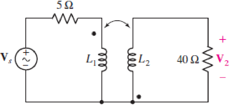
Obtain an expression for V2/Vs in the circuit of Fig. 13.68 if (a) L1 = 100 mH, L2 = 500 mH, and M is its maximum possible value; (b) L1 = 5L2 = 1.4 H and k = 87% of its maximum possible value; (c) the two coils can be treated as an ideal transformer, the left-hand coil having 500 turns and the right-hand coil having 10,000 turns.
FIGURE 13.68
(a)
Find the expression for
Answer to Problem 54E
The expression for
Explanation of Solution
Given data:
Refer to Figure 13.68 in the textbook for the given circuit.
The circuit parameters are given as follows:
Formula used:
Write the expression for reactance due to inductive coil of self-inductance as follows:
Here,
Write the expression for reactance due to inductive coil of mutual-inductance as follows:
Here,
Write the expression for mutual inductance as follows:
Here,
Calculation:
The maximum possible value of
Substitute 1 for
Observer the dot notation in the circuit, use the expression in Equations (1), (2), and apply KVL to the primary winding-loop in the given circuit as follows:
Simplify the expression as follows:
Substitute
Observer the dot notation, use the expression in Equations (1), (2), and apply KVL to the secondary winding-loop in the given circuit as follows:
Substitute
Substitute
From the given circuit, write the expression for
Rearrange the expression as follows:
Substitute
Rearrange the expression as follows:
Conclusion:
Thus, the expression for
(b)
Find the expression for
Answer to Problem 54E
The expression for
Explanation of Solution
Given data:
The circuit parameters are given as follows:
Calculation:
Find the value of
Substitute 0.87 for
Substitute 1.4 H for
Substitute 0.28 H for
Substitute
Substitute
Rearrange the expression as follows:
Conclusion:
Thus, the expression for
(c)
Find the expression for
Answer to Problem 54E
The expression for
Explanation of Solution
Given data:
The circuit parameters are given as follows:
Formula used:
Write the expression for transformer ratio as follows:
Here,
Write the expression for input impedance of the transformer as follows:
Here,
From the given circuit, write the expression for current through primary winding of the transformer as follows:
Calculation:
Substitute 500 for
Substitute 20 for
Substitute
From the given circuit, write the expression for
From Equation (12), substitute
Write the expression for transformer ratio in terms of voltages as follows:
Substitute 20 for
Rearrange the expression as follows:
Conclusion:
Thus, the expression for
Want to see more full solutions like this?
Chapter 13 Solutions
Loose Leaf for Engineering Circuit Analysis Format: Loose-leaf


 Introductory Circuit Analysis (13th Edition)Electrical EngineeringISBN:9780133923605Author:Robert L. BoylestadPublisher:PEARSON
 Delmar's Standard Textbook Of ElectricityElectrical EngineeringISBN:9781337900348Author:Stephen L. HermanPublisher:Cengage Learning
 Programmable Logic ControllersElectrical EngineeringISBN:9780073373843Author:Frank D. PetruzellaPublisher:McGraw-Hill Education
 Fundamentals of Electric CircuitsElectrical EngineeringISBN:9780078028229Author:Charles K Alexander, Matthew SadikuPublisher:McGraw-Hill Education
 Electric Circuits. (11th Edition)Electrical EngineeringISBN:9780134746968Author:James W. Nilsson, Susan RiedelPublisher:PEARSON
 Engineering ElectromagneticsElectrical EngineeringISBN:9780078028151Author:Hayt, William H. (william Hart), Jr, BUCK, John A.Publisher:Mcgraw-hill Education,