
Loose Leaf for Engineering Circuit Analysis Format: Loose-leaf
9th Edition
ISBN: 9781259989452
Author: Hayt
Publisher: Mcgraw Hill Publishers
expand_more
expand_more
format_list_bulleted
Videos
Textbook Question
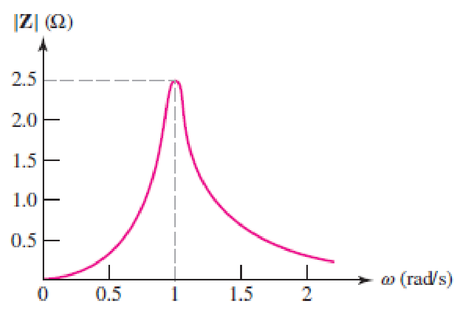
Chapter 15, Problem 33E
A parallel RLC circuit is constructed such that it has the impedance magnitude characteristic plotted in Fig. 15.60. (a) Determine the resistor value. (b) Determine the capacitor value if a 1 H inductor was used. (c) Obtain values for the bandwidth. Q0, and both the low half-power frequency and the high half-power frequency.
Expert Solution & Answer
Want to see the full answer?
Check out a sample textbook solution
Students have asked these similar questions
1. A series RLC circuit has a Q of 75 and a pass band between half-power frequencies of 160 cps. Calculate the frequency of resonance and upper and lower frequencies of the pass band.
2. A 15.9 uF capacitor and a 15.1 mH inductor are connected in parallel. In series with these units are a variable resistor R and an adjustable device X, joined in series. (a) Determine the kind and size of device X (inductance in Henry or capacitance in Farad) when the circuit is connected to a 50 volt 400 cps source and is adjusted to resonance. (b) For the resonant condition, calculate the value of R if the voltage drop across the paralleled units is to be 100 volts.
3. An impedance coil having a resistance of 30 ohms and a 50 cps inductive reactance of 33.3 ohms is connected to a 125 volt 60 cps source. A series circuit consisting of a 20 ohm resistor and a variable capacitor is then connected in parallel with the coil. (a) for what values of capacitance will the circuit be in resonance? (b)…
Q.5: b. Choose the suitable choice for nine of the following sentences.
1. In order to lune a parallel resonant circuit to a lower frequency. the capacitor must........
> Be decrease.
a. Be increase
d. Remain the same.
e. Be Zero.
2 In series as well as parallel resonance circuit, increase in resistance would cause the bandwidth is......
a. Increase in both circuits. (h. Decrease in series eircuit and increase in parallel circuit.
d. lucrease in series circuit and decrease in parallel circuit.
circuit.
e Decrease in both circuits.
3. In a very low frequency a series resonance circuit behaves as almost purely
a. Resistive.
c. Inductive. d. Inductive and capacitive.
b. Capacitive:
4. Real part of the total impedance at resonance for complicated AC circuit is
a. Positive Value.
b. Zero Value.
5. For admittance locus the maximum obtained power factor is depend on:
a. Maximum current
b. Maximum voltage
c. Minimum power 4. Minimum angle
6. Any non-sinusoidal symmetrical waves are basically…
For the following given circuit;
b) find Av and Avs in the medium frequency range.c) find fHi and fh0.d) draw the frequency response for the high frequency region using the bode graph and determine the cutting frequency.
Chapter 15 Solutions
Loose Leaf for Engineering Circuit Analysis Format: Loose-leaf
Ch. 15.1 - Write an expression for the transfer function of...Ch. 15.2 - Calculate HdB at = 146 rad/s if H(s) equals (a)...Ch. 15.2 - Prob. 3PCh. 15.2 - Draw the Bode phase plot for the transfer function...Ch. 15.2 - Construct a Bode magnitude plot for H(s) equal to...Ch. 15.2 - Draw the Bode phase plot for H(s) equal to (a)...Ch. 15.2 - Prob. 7PCh. 15.3 - A parallel resonant circuit is composed of the...Ch. 15.3 - Prob. 9PCh. 15.4 - A marginally high-Q parallel resonant circuit has...
Ch. 15.5 - A series resonant circuit has a bandwidth of 100...Ch. 15.6 - Referring to the circuit of Fig. 15.25a, let R1 =...Ch. 15.6 - Prob. 13PCh. 15.6 - Prob. 14PCh. 15.6 - The series combination of 10 and 10 nF is in...Ch. 15.7 - A parallel resonant circuit is defined by C = 0.01...Ch. 15.8 - Design a high-pass filter with a cutoff frequency...Ch. 15.8 - Design a bandpass filter with a low-frequency...Ch. 15.8 - Design a low-pass filter circuit with a gain of 30...Ch. 15 - For the RL circuit in Fig. 15.52, (a) determine...Ch. 15 - For the RL circuit in Fig. 15.52, switch the...Ch. 15 - Examine the series RLC circuit in Fig. 15.53, with...Ch. 15 - For the circuit in Fig. 15.54, (a) derive an...Ch. 15 - For the circuit in Fig. 15.55, (a) derive an...Ch. 15 - For the circuit in Fig. 15.56, (a) determine the...Ch. 15 - For the circuit in Fig. 15.57, (a) determine the...Ch. 15 - Sketch the Bode magnitude and phase plots for the...Ch. 15 - Use the Bode approach to sketch the magnitude of...Ch. 15 - If a particular network is described by transfer...Ch. 15 - Use MATLAB to plot the magnitude and phase Bode...Ch. 15 - Determine the Bode magnitude plot for the...Ch. 15 - Determine the Bode magnitude and phase plot for...Ch. 15 - Prob. 15ECh. 15 - Prob. 16ECh. 15 - For the circuit of Fig. 15.56, construct a...Ch. 15 - Construct a magnitude and phase Bode plot for the...Ch. 15 - For the circuit in Fig. 15.54, use LTspice to...Ch. 15 - For the circuit in Fig. 15.55, use LTspice to...Ch. 15 - Prob. 21ECh. 15 - A certain parallel RLC circuit is built using...Ch. 15 - A parallel RLC network is constructed using R = 5...Ch. 15 - Prob. 24ECh. 15 - Delete the 2 resistor in the network of Fig....Ch. 15 - Delete the 1 resistor in the network of Fig....Ch. 15 - Prob. 28ECh. 15 - Prob. 29ECh. 15 - Prob. 30ECh. 15 - A parallel RLC network is constructed with a 200 H...Ch. 15 - Prob. 32ECh. 15 - A parallel RLC circuit is constructed such that it...Ch. 15 - Prob. 34ECh. 15 - Prob. 35ECh. 15 - An RLC circuit is constructed using R = 5 , L = 20...Ch. 15 - Prob. 37ECh. 15 - Prob. 38ECh. 15 - For the network of Fig. 15.25a, R1 = 100 , R2 =...Ch. 15 - Assuming an operating frequency of 200 rad/s, find...Ch. 15 - Prob. 41ECh. 15 - Prob. 42ECh. 15 - For the circuit shown in Fig. 15.64, the voltage...Ch. 15 - Prob. 44ECh. 15 - Prob. 45ECh. 15 - Prob. 46ECh. 15 - The filter shown in Fig. 15.66a has the response...Ch. 15 - Prob. 48ECh. 15 - Examine the filter for the circuit in Fig. 15.68....Ch. 15 - Examine the filter for the circuit in Fig. 15.69....Ch. 15 - (a)Design a high-pass filter with a corner...Ch. 15 - (a) Design a low-pass filter with a break...Ch. 15 - Prob. 53ECh. 15 - Prob. 54ECh. 15 - Design a low-pass filter characterized by a...Ch. 15 - Prob. 56ECh. 15 - The circuit in Fig. 15.70 is known as a notch...Ch. 15 - (a) Design a two-stage op amp filter circuit with...Ch. 15 - Design a circuit which removes the entire audio...Ch. 15 - Prob. 61ECh. 15 - If a high-pass filter is required having gain of 6...Ch. 15 - (a) Design a second-order high-pass Butterworth...Ch. 15 - Design a fourth-order high-pass Butterworth filter...Ch. 15 - (a) Design a Sallen-Key low-pass filter with a...Ch. 15 - (a) Design a Sallen-Key low-pass filter with a...Ch. 15 - A piezoelectric sensor has an equivalent circuit...Ch. 15 - Design a parallel resonant circuit for an AM radio...Ch. 15 - The network of Fig. 15.72 was implemented as a...Ch. 15 - Determine the effect of component tolerance on the...
Additional Engineering Textbook Solutions
Find more solutions based on key concepts
The voltage source of the circuit shown in Fig. P1.29 is given by s(t)=25cos(4104t45)(V). Obtain an expression ...
Fundamentals of Applied Electromagnetics (7th Edition)
Three point charges of equal magnitude q, that will yield a zero net electric field at the origin.
Engineering Electromagnetics
When travelers from the USA and Canada visit Europe, they encounter a different power distribution system. Wall...
Electric machinery fundamentals
Identify the type of input and output configuration for each diff-amp in Figure 18-35.
Electronics Fundamentals: Circuits, Devices & Applications
For the “tank” circuit in Fig. 14.79, find the resonant frequency.
Figure 14.79
For Probs. 14.39, 14.71, and 1...
Fundamentals of Electric Circuits
Assume a telephone signal travels through a cable at two-thirds the speed of light. How long does it take the s...
Electric Circuits (10th Edition)
Knowledge Booster


Learn more about
Need a deep-dive on the concept behind this application? Look no further. Learn more about this topic, electrical-engineering and related others by exploring similar questions and additional content below.Similar questions
- H.W: A resistor of resistance R=1000 2 is maintained at 17 °C and it shunted by 100 µH inductor. Determine the rms noise voltage across the inductor over a frequency bandwidth of: Ans: 182 x10-9 volt i) ii) iii) 15.9 kHz Ans: 9.22 x10⁻⁸ volt Ans: 2.34 x10⁻⁶ volt 159 kHz 1590 kHzarrow_forwardHelp plz: Design a Wein bridge oscillator to generate a sinusoidal waveform of frequency 5KHz.arrow_forwardGiven the parallel-connected RLC circuit below: a. Calculate the resonance frequency. b. Calculate the supply current, and the individual current flowing through the coil and capacitor, when the circuit is resonating. C. Draw the supply current transient along the frequency-axis when the input frequency sweeps from 0Hz to the resonant frequency and beyond (>1.5fo). d. Calculate the Q-factor. e. Draw the bandwidth profiles for y-axis being current (A), voltage (V), and maximum k-value (impedance), and it's respective cut-off frequencies. V = 520°V, rms 0.2 Ω M 100MH3 coil Figure 2. Parallel-connected RLC circuit. 2 μFarrow_forward
- 1. A parallel R-L-C circuit is fed by a constant current source of variable frequency. The circuit resonates at 100 kHz and the Q-factor measured at this frequency is 5. Find the frequencies at which the amplitude of the voltage across the circuit falls to (a) 70.7% (b) 50% of the resonant frequency amplitude. [(a) 90.5 kHz ; 110.5 kHz (b) 84.18 kHz ; 118.8 kHz]arrow_forwardH.W: A resistor of resistance R=1000 N is maintained at 17 °C and it shunted by 100 µH inductor. Determine the rms noise voltage across the inductor over a frequency bandwidth of: Ans: 182 x10-9 volt i) ii) iii) 15.9 kHz 159 kHz Ans: 9.22 x10⁻⁸ volt 1590 kHz Ans: 2.34 x10⁻⁶ voltarrow_forwardA coil of inductance 15 mH and resistance 75 is connected in series with a 25 9 resistor and a variable capacitor. The combination is connected across a voltage supply of magnitude 80 V and frequency 800 Hz. Determine: a. The value of capacitance to tune the circuit to resonance b. The quality factor of the circuit c. The bandwidth of the circuit d. The exact values of the half power frequencies. e. The voltage across the coil at the upper and lower cut-off frequenciesarrow_forward
- 1. An impedance coil takes 144 watts at a lagging power factor of 0.6. What value of capacitanceand resistance should be connected in series with the coil if the power input to the latter is toremain unchanged and the overall power factor is to be unity (in resonance)? The circuit isenergized by a 120 volt, 60 cps source.2. A series RLC circuit has a Q of 75 and a pass band between half-power frequencies of 160 cps.Calculate the frequency of resonance and upper and lower frequencies of the pass band.3. An impedance coil having a resistance of 30 ohms and a 50 cps inductive reactance of 33.3 ohmsis connected to a 125 volt 60 cps source. A series circuit consisting of a 20 ohm resistor and avariable capacitor is then connected in parallel with the coil. (a) for what values of capacitancewill the circuit be in resonance? (b) calculate the two values of line current for the condition ofresonance.4. A parallel-series filter like that of Fig. 13.10b in the scanned copy of the on page 364 is…arrow_forwardb. Choose the suitable choice foL ping of the following sentences 18 Maces 1. In order to tune a parallel resonant circuit to a lewer frequency the capacitor must a. Be increase. b. Be decrease. . BeZero. Remain the same 2. Ina very low frequency a series resonance behaves as Imost purely .......... circuit a Resistive. b Capacitive. . Inductive. d. Inductive and capacitive 3. Real part of the total impedance at resonance for complicated AC circuit is a. Positive Value. b. Zero Value. Negative Value. d. Complex value 4. For admittance locus the maximum obtained power factor is depend on a Maximum current b. Maximum voltage . Minimum power d. Minimum angle 5 Any non sinusoidal symmetrical waves are basically composite from fundamental wave plas .. of harmonics waves. aodd b. even . odd even d odd of even 6. If we append an inductance in series to an RL series circuit the time constant will be a Increases b. Decreases. Increases and Decreases. Increases or Decreases 7. The double energy…arrow_forwardProblem Solving Coverage: BJT Small Signal Analysis Instruction: WRITE the complete solutions and box your final answer. Use three (3) decimal places in your final answer. For the figure below: H 6.8 µF Determine the following: B. AC Analysis: www ww 68 kf 16 k2 16 V 2.2kQ 4. Solve the value of Zi, Zo, Av and Ai 2. Solve for re 3. Derive the equation of Zi, Zo, Av and Ai 0.75 k 6.8 µF H 3-100 10 µF 5.6 karrow_forward
- O d. FM demodulator Choose the correct statement(s) that describe the diagram below. - x,(1) Bandpass filter Envelope detector Limiter Differentiator Select one or more: a. FM Demodulator b. Narrowband to wideband conversion OC. PM Demodulator Od. Linear PLL model e. FM Discriminator with bandpass limiter A third-order PLL can track a frequency-ramp with zero steady-state nhase errorarrow_forwardV:OV 3G !!.: Classroom > docs.google.com • * الاسم الرباعي الكامل Your answer Engineering and Numerical Analysis Lecture: Safa Al-waily 01| plot the Amplidude s phase spectyum (signal & double side) Q2 |Fimd x plot h complex form of (Fis) for he fenetion. Scanned by TapScanner 1 Add file Submit Clear form Never submit passwords through Google Forms. + •.. 5arrow_forward15. A parallel resonant circuit is resonant at 400 Hz with Qo If a current of 2 mA is applied to the circuit, use approximate methods to find the cyclic frequency of the current if (a) the voltage across the circuit has a magnitude of 0.5 V; (b) the resistor current has a magnitude of 0.5 mA. = 8 and R = 500 S2. 443.3 and 356.7 Hz 496.8 and 303.2 Hz|arrow_forward
arrow_back_ios
SEE MORE QUESTIONS
arrow_forward_ios
Recommended textbooks for you
 Introductory Circuit Analysis (13th Edition)Electrical EngineeringISBN:9780133923605Author:Robert L. BoylestadPublisher:PEARSON
 Delmar's Standard Textbook Of ElectricityElectrical EngineeringISBN:9781337900348Author:Stephen L. HermanPublisher:Cengage Learning
 Programmable Logic ControllersElectrical EngineeringISBN:9780073373843Author:Frank D. PetruzellaPublisher:McGraw-Hill Education
 Fundamentals of Electric CircuitsElectrical EngineeringISBN:9780078028229Author:Charles K Alexander, Matthew SadikuPublisher:McGraw-Hill Education
 Electric Circuits. (11th Edition)Electrical EngineeringISBN:9780134746968Author:James W. Nilsson, Susan RiedelPublisher:PEARSON
 Engineering ElectromagneticsElectrical EngineeringISBN:9780078028151Author:Hayt, William H. (william Hart), Jr, BUCK, John A.Publisher:Mcgraw-hill Education,
Introductory Circuit Analysis (13th Edition)
Electrical Engineering
ISBN:9780133923605
Author:Robert L. Boylestad
Publisher:PEARSON
Delmar's Standard Textbook Of Electricity
Electrical Engineering
ISBN:9781337900348
Author:Stephen L. Herman
Publisher:Cengage Learning
Programmable Logic Controllers
Electrical Engineering
ISBN:9780073373843
Author:Frank D. Petruzella
Publisher:McGraw-Hill Education
Fundamentals of Electric Circuits
Electrical Engineering
ISBN:9780078028229
Author:Charles K Alexander, Matthew Sadiku
Publisher:McGraw-Hill Education
Electric Circuits. (11th Edition)
Electrical Engineering
ISBN:9780134746968
Author:James W. Nilsson, Susan Riedel
Publisher:PEARSON
Engineering Electromagnetics
Electrical Engineering
ISBN:9780078028151
Author:Hayt, William H. (william Hart), Jr, BUCK, John A.
Publisher:Mcgraw-hill Education,
Resonance Circuits: LC Inductor-Capacitor Resonating Circuits; Author: Physics Videos by Eugene Khutoryansky;https://www.youtube.com/watch?v=Mq-PF1vo9QA;License: Standard YouTube License, CC-BY