
Videos
For the circuit in Fig. 15.55, (a) derive an algebraic expression for the transfer function H(jω) = iout/vin in terms of circuit components R1, R2, L1, and L2; (b) evaluate the the magnitude of H(jω) at frequencies of 10 kHz, 1 MHz, and 100 MHz for the case where R1 = 3 kΩ, R2 = 12 kΩ, L1 = 5 mH, and L2 = 8 mH; (c) qualitatively, explain the behavior of the transfer function magnitude frequency response.
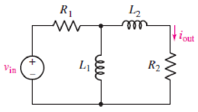
■ FIGURE 15.55
(a)
Find an algebraic expression for the transfer function
Answer to Problem 5E
The transfer function
Explanation of Solution
Given data:
Refer to Figure 15.55 in the textbook.
Formula used:
Write the expression to calculate the impedance of the passive elements resistor and inductor.
Here,
Calculation:
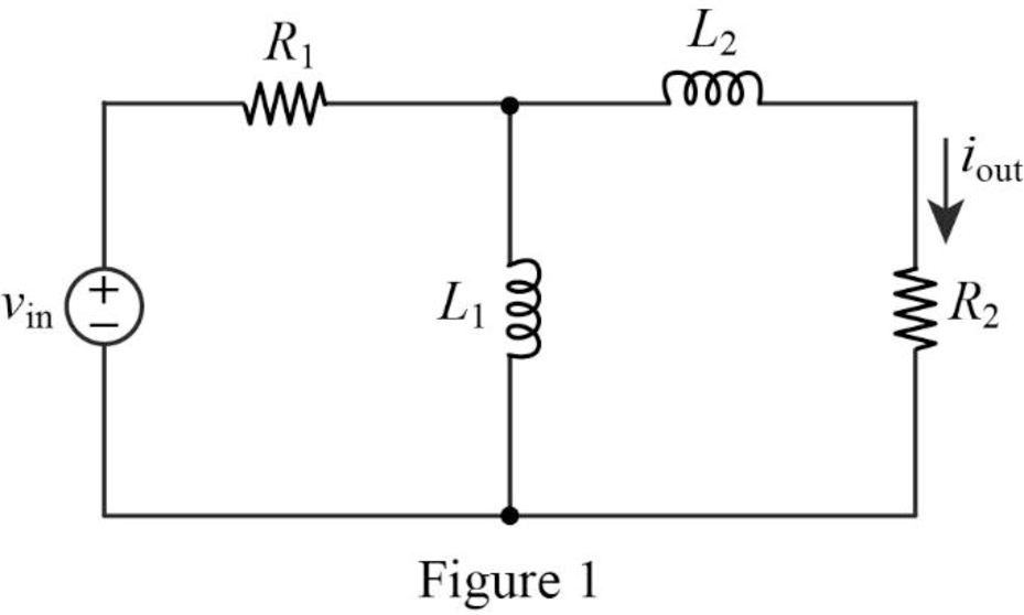
The given circuit is redrawn as Figure 1.
The impedance circuit of the Figure 1 is drawn as Figure 2 using the equations (1) and (2).
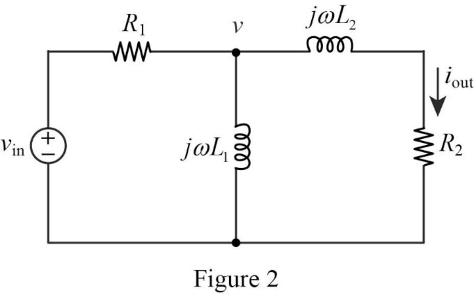
Write the general expression to calculate the transfer function of the circuit in Figure 2.
Here,
Use nodal analysis on node
Rearrange the above equation to find
The output current
Substitute
Simplify the above equation to find
Substitute
Conclusion:
Thus, the transfer function
(b)
Find the value of magnitude of
Answer to Problem 5E
The value of magnitude of the transfer function
Explanation of Solution
Given data:
The value of the resistor 1
The value of the resistor 2
The value of the inductor 1
The value of the inductor 2
Formula used:
Write the expression to calculate the angular frequency.
Here,
Calculation:
From part (a), the transfer function is,
Substitute
Substitute
For frequency of 10 kHz:
Substitute
Take magnitude for above equation to find
For frequency of 1 MHz:
Substitute
Take magnitude for above equation to find
For frequency of 100 MHz:
Substitute
Take magnitude for above equation to find
Conclusion:
Thus, the value of magnitude of the transfer function
(c)
Explain the behavior of the transfer function magnitude frequency response.
Explanation of Solution
Discussion:
At lower frequencies
It is clear that the current
The magnitude approaches zero at low and high frequencies and at medium frequencies, the magnitude approaches maximum value. It implies the characteristics of the band-pass filter.
Conclusion:
Thus, the behavior of the transfer function magnitude frequency response is explained.
Want to see more full solutions like this?
Chapter 15 Solutions
Loose Leaf for Engineering Circuit Analysis Format: Loose-leaf
Additional Engineering Textbook Solutions
Fundamentals of Electric Circuits
Basic Engineering Circuit Analysis
ANALYSIS+DESIGN OF LINEAR CIRCUITS(LL)
Electric Motors and Control Systems
Electric Circuits. (11th Edition)
Introductory Circuit Analysis (13th Edition)


- Problem Solving Coverage: BJT Small Signal Analysis Instruction: WRITE the complete solutions and box your final answer. Use three (3) decimal places in your final answer. For the figure below: H 6.8 µF www ww 16 k2 16 2.2kQ 4. Solve the value of Zi, Zo, Av and Ai 6.8 µF HH 3-100 0.75 k 10µF Determine the following: A. DC Analysis: Determine the value of IE and VCE B. AC Analysis: 1. Draw/sketch the AC Equivalent Circuit using re model 2. Solve for re 3. Derive the equation of Zi, Zo, Av and Ai 5.6 karrow_forward1. A parallel R-L-C circuit is fed by a constant current source of variable frequency. The circuit resonates at 100 kHz and the Q-factor measured at this frequency is 5. Find the frequencies at which the amplitude of the voltage across the circuit falls to (a) 70.7% (b) 50% of the resonant frequency amplitude. [(a) 90.5 kHz ; 110.5 kHz (b) 84.18 kHz ; 118.8 kHz]arrow_forwardO d. FM demodulator Choose the correct statement(s) that describe the diagram below. - x,(1) Bandpass filter Envelope detector Limiter Differentiator Select one or more: a. FM Demodulator b. Narrowband to wideband conversion OC. PM Demodulator Od. Linear PLL model e. FM Discriminator with bandpass limiter A third-order PLL can track a frequency-ramp with zero steady-state nhase errorarrow_forward
- a) Compute the transfer function T(w), the absolute value, and phase at resonant frequency. b) What kind of filter is this? Please answer in typing format please ASAParrow_forwardL Vi R Vo Figure 3 The circuit given in Figure 3 H(jw) = V obtaining the transfer function frequency response of the circuit Draw H(jw) = =?arrow_forwardocs.google.com/forms/d/e/1FAIPQLS FM signal is better than AM signal because * O stereo techniques may apply O more immune to noise O All of the above O Less adjacent channel interference The signal can be reconstructed O At Nyquist rate O Above Nyquist rate O At & above the Nyquist rate O Below Nyquist rate PAM signal can be extracted by using. O LPF O HPF O PLL O PWMarrow_forward
- 15.5 What is the bandwidth of a band-pass filter whose critical frequencies are 3.2kHz and 3.9kHz? What is the Q of this filter?arrow_forwardFind the transfer function for the circuit shown in figure 1. Plot the amplitude graph of 2logh10hw and the phase angle graph of H(jw)? Calculate the actual cutoff frequency? Calculate the true phase angle at the cutoff frequency?arrow_forwardGiven range of frequencies for a channel (as shown in the figure) and SNR = 15, based on Nyquist's formula, how many signal levels are required? -3 dB 2 MHz 10 MHzarrow_forward
- Derive and plot the magnitude and phase responses of the first order difference system, y[n] = x[n]–x[n − 1]. ..arrow_forward15.5 shows the Bode magnitude plot of a high-pass filter. Using theactive high-pass filter circuit in 15.4, calculate values of R1 and R2 thatproduce the desired magnitude response. Use a 0.1 μF capacitor. If a 10 kΩload resistor is added to this filter, how will the magnitude response change?arrow_forwardQ) Draw and find the equivalent cct, low and high frequency responses, and overall gain (Av)? Hint: Use any value you want for the Rs and RL. BDc = Bac = 125 Che = 25 pF Cbc = 10 pF Vcc %3D ас +9 V %3D Rc C3 220 N Vout R1 12 kΩ 1 µF RL Ω 1 µF Ω Rs C2 10 μF RE R2 4.7 k2 100 N Vinarrow_forward
 Introductory Circuit Analysis (13th Edition)Electrical EngineeringISBN:9780133923605Author:Robert L. BoylestadPublisher:PEARSON
 Delmar's Standard Textbook Of ElectricityElectrical EngineeringISBN:9781337900348Author:Stephen L. HermanPublisher:Cengage Learning
 Programmable Logic ControllersElectrical EngineeringISBN:9780073373843Author:Frank D. PetruzellaPublisher:McGraw-Hill Education
 Fundamentals of Electric CircuitsElectrical EngineeringISBN:9780078028229Author:Charles K Alexander, Matthew SadikuPublisher:McGraw-Hill Education
 Electric Circuits. (11th Edition)Electrical EngineeringISBN:9780134746968Author:James W. Nilsson, Susan RiedelPublisher:PEARSON
 Engineering ElectromagneticsElectrical EngineeringISBN:9780078028151Author:Hayt, William H. (william Hart), Jr, BUCK, John A.Publisher:Mcgraw-hill Education,