
Loose Leaf for Engineering Circuit Analysis Format: Loose-leaf
9th Edition
ISBN: 9781259989452
Author: Hayt
Publisher: Mcgraw Hill Publishers
expand_more
expand_more
format_list_bulleted
Videos
Textbook Question
Chapter 15, Problem 3E
Examine the series RLC circuit in Fig. 15.53, with R = 100 Ω, L = 5 mH, and C = 2 μF. Calculate the magnitude of the transfer function H(jω) = vout/vin at frequencies of 0, 2 kHz. and ∞ for the three cases where (a) vout = vR, (b) vout = vL,. and (c) vout = vC.
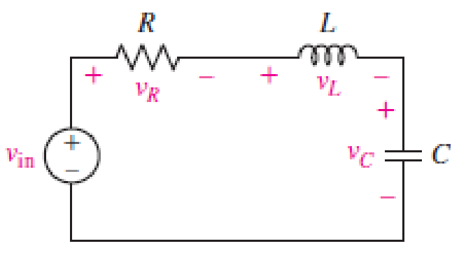
FIGURE. 15.53
Expert Solution & Answer
Want to see the full answer?
Check out a sample textbook solution
Students have asked these similar questions
A series circuit with R = 10 2, L = 0.1 H and C =
%3D
%3D
%3D
50 µF has an applied voltage V = 50 L0° with a
variable frequency. Find the resonant frequency,
the value of frequency at which maximum voltage
occurs across the inductor and the value of fre-
quency at which maximum voltage occurs across the
сараcitor.
Problem Solving
Coverage: BJT Small Signal Analysis
Instruction:
WRITE the complete solutions and box your final answer. Use three (3) decimal places in your
final answer.
For the figure below:
H
6.8 µF
Determine the following:
B. AC Analysis:
www
ww
68 kf
16 k2
16 V
2.2kQ
4. Solve the value of Zi, Zo, Av and Ai
2. Solve for re
3. Derive the equation of Zi, Zo, Av and Ai
0.75 k
6.8 µF
H
3-100
10 µF
5.6 k
1. A parallel R-L-C circuit is fed by a constant
current source of variable frequency. The circuit
resonates at 100 kHz and the Q-factor
measured at this frequency is 5. Find the
frequencies at which the amplitude of the
voltage across the circuit falls to (a) 70.7% (b)
50% of the resonant frequency amplitude. [(a)
90.5 kHz ; 110.5 kHz (b) 84.18 kHz ; 118.8 kHz]
Chapter 15 Solutions
Loose Leaf for Engineering Circuit Analysis Format: Loose-leaf
Ch. 15.1 - Write an expression for the transfer function of...Ch. 15.2 - Calculate HdB at = 146 rad/s if H(s) equals (a)...Ch. 15.2 - Prob. 3PCh. 15.2 - Draw the Bode phase plot for the transfer function...Ch. 15.2 - Construct a Bode magnitude plot for H(s) equal to...Ch. 15.2 - Draw the Bode phase plot for H(s) equal to (a)...Ch. 15.2 - Prob. 7PCh. 15.3 - A parallel resonant circuit is composed of the...Ch. 15.3 - Prob. 9PCh. 15.4 - A marginally high-Q parallel resonant circuit has...
Ch. 15.5 - A series resonant circuit has a bandwidth of 100...Ch. 15.6 - Referring to the circuit of Fig. 15.25a, let R1 =...Ch. 15.6 - Prob. 13PCh. 15.6 - Prob. 14PCh. 15.6 - The series combination of 10 and 10 nF is in...Ch. 15.7 - A parallel resonant circuit is defined by C = 0.01...Ch. 15.8 - Design a high-pass filter with a cutoff frequency...Ch. 15.8 - Design a bandpass filter with a low-frequency...Ch. 15.8 - Design a low-pass filter circuit with a gain of 30...Ch. 15 - For the RL circuit in Fig. 15.52, (a) determine...Ch. 15 - For the RL circuit in Fig. 15.52, switch the...Ch. 15 - Examine the series RLC circuit in Fig. 15.53, with...Ch. 15 - For the circuit in Fig. 15.54, (a) derive an...Ch. 15 - For the circuit in Fig. 15.55, (a) derive an...Ch. 15 - For the circuit in Fig. 15.56, (a) determine the...Ch. 15 - For the circuit in Fig. 15.57, (a) determine the...Ch. 15 - Sketch the Bode magnitude and phase plots for the...Ch. 15 - Use the Bode approach to sketch the magnitude of...Ch. 15 - If a particular network is described by transfer...Ch. 15 - Use MATLAB to plot the magnitude and phase Bode...Ch. 15 - Determine the Bode magnitude plot for the...Ch. 15 - Determine the Bode magnitude and phase plot for...Ch. 15 - Prob. 15ECh. 15 - Prob. 16ECh. 15 - For the circuit of Fig. 15.56, construct a...Ch. 15 - Construct a magnitude and phase Bode plot for the...Ch. 15 - For the circuit in Fig. 15.54, use LTspice to...Ch. 15 - For the circuit in Fig. 15.55, use LTspice to...Ch. 15 - Prob. 21ECh. 15 - A certain parallel RLC circuit is built using...Ch. 15 - A parallel RLC network is constructed using R = 5...Ch. 15 - Prob. 24ECh. 15 - Delete the 2 resistor in the network of Fig....Ch. 15 - Delete the 1 resistor in the network of Fig....Ch. 15 - Prob. 28ECh. 15 - Prob. 29ECh. 15 - Prob. 30ECh. 15 - A parallel RLC network is constructed with a 200 H...Ch. 15 - Prob. 32ECh. 15 - A parallel RLC circuit is constructed such that it...Ch. 15 - Prob. 34ECh. 15 - Prob. 35ECh. 15 - An RLC circuit is constructed using R = 5 , L = 20...Ch. 15 - Prob. 37ECh. 15 - Prob. 38ECh. 15 - For the network of Fig. 15.25a, R1 = 100 , R2 =...Ch. 15 - Assuming an operating frequency of 200 rad/s, find...Ch. 15 - Prob. 41ECh. 15 - Prob. 42ECh. 15 - For the circuit shown in Fig. 15.64, the voltage...Ch. 15 - Prob. 44ECh. 15 - Prob. 45ECh. 15 - Prob. 46ECh. 15 - The filter shown in Fig. 15.66a has the response...Ch. 15 - Prob. 48ECh. 15 - Examine the filter for the circuit in Fig. 15.68....Ch. 15 - Examine the filter for the circuit in Fig. 15.69....Ch. 15 - (a)Design a high-pass filter with a corner...Ch. 15 - (a) Design a low-pass filter with a break...Ch. 15 - Prob. 53ECh. 15 - Prob. 54ECh. 15 - Design a low-pass filter characterized by a...Ch. 15 - Prob. 56ECh. 15 - The circuit in Fig. 15.70 is known as a notch...Ch. 15 - (a) Design a two-stage op amp filter circuit with...Ch. 15 - Design a circuit which removes the entire audio...Ch. 15 - Prob. 61ECh. 15 - If a high-pass filter is required having gain of 6...Ch. 15 - (a) Design a second-order high-pass Butterworth...Ch. 15 - Design a fourth-order high-pass Butterworth filter...Ch. 15 - (a) Design a Sallen-Key low-pass filter with a...Ch. 15 - (a) Design a Sallen-Key low-pass filter with a...Ch. 15 - A piezoelectric sensor has an equivalent circuit...Ch. 15 - Design a parallel resonant circuit for an AM radio...Ch. 15 - The network of Fig. 15.72 was implemented as a...Ch. 15 - Determine the effect of component tolerance on the...
Additional Engineering Textbook Solutions
Find more solutions based on key concepts
Does the severity of an electric shock increase ordecrease with eh of the following changes? a. A decrease in t...
Electric Motors and Control Systems
The current source in the circuit shown generates the current pulse
Find (a) v (0); (b) the instant of time gr...
Electric Circuits. (11th Edition)
The voltage source of the circuit shown in Fig. P1.29 is given by s(t)=25cos(4104t45)(V). Obtain an expression ...
Fundamentals of Applied Electromagnetics (7th Edition)
Analog Voltmeter Design Figure P2-98(a) shows a voltmeter circuit consisting of a D'Arsonval meter, two series ...
ANALYSIS+DESIGN OF LINEAR CIRCUITS(LL)
Explain the main function of each of the following major components of a PLC: a. Processor module (CPU) b. I/O ...
Programmable Logic Controllers
When travelers from the USA and Canada visit Europe, they encounter a different power distribution system. Wall...
Electric machinery fundamentals
Knowledge Booster


Learn more about
Need a deep-dive on the concept behind this application? Look no further. Learn more about this topic, electrical-engineering and related others by exploring similar questions and additional content below.Similar questions
- A supply voltage of 3 V is applied to a series R–L–C circuit whose resistance is 12 ohms , inductance is 7.5 mH and capacitance is 0.5µF. Determine (a) the current flowing at resonance, (b) the current flowing at a frequency 2.5% below the resonant frequency and (c) the impedance of the circuit when the frequency is 1% lower than the resonant frequency.arrow_forwardA 15.9-uF capacitor and a 15.1-mH inductor are connected in parallel. In series with these units are a variable resistor R and an adjustable reactive device X. joined inseries. (a) Determine the kind and size of device X inductance in henrys orcapacitance in μF) when the circuit is connected to a 50-volf 400-cycle source and is adjusted to resonance. (b) For the resonant condition calculate the value of R if the voltage drop across the paralleled units is to be 100 V.arrow_forwardPlot the magnitude and phase plot for the following transfer function, use the templates from the class notes module so as to provide somewhat an accurate representation of the magnitude and phase plots. H (ju) 10 jw (0.01jw+1) (0.1jw+1)arrow_forward
- Q. For the circuit shown, calculate the lower and the upper critical frequency due to the input circuit. Vcc +20 V Rc C3 2.2 kn Bac = 150 Cpe = 4 pF V out R1 33 k2 %3D Che = 10 pF %3D 0.1 μF RL 5.6 k2 R 0.1 uF 50 N R2 4.7 k RE 560 10 μF Vinarrow_forwardA circuit of the series LRC has R = 4 Kohm e L = 6mH. (a) What should be the value of capacitance to produce a resonance at the frequency of 40 kHz? (b) What is the maximum current rms in the circuit when is the voltage rms of the source 150 V? (c) the impedance of the inductor and capacitor, and (d) the power dissipated in the circuitarrow_forwardHelp plz: Design a Wein bridge oscillator to generate a sinusoidal waveform of frequency 5KHz.arrow_forward
- Given the series RLC circuit in the following figure: (a) Derive the expression for the half-power frequencies, the resonant frequency, the bandwidth, and the quality factor. (b) Compute the quantities in part (a) if R = 10, L = 50mH, and C = 10μF i(t) R L Vin(t) Carrow_forwardA series L–R–C circuit has a supply input of 5 volts. Given that inductance, L = 5 mH, resistance, R = 75ohm and capacitance, C = 0.2µF, determine (a) the resonant frequency, (b) the value of voltage across the capacitor at the resonant frequency, (c) the frequency at which the p.d. across the capacitance is a maximum and (d) the value of the maximum voltage across the capacitor. A capacitor having a Q-factor of 250 is con nected in series with a coil which has a Q-factor of 80. Calculate the overall Q-factor of the circuit.arrow_forwardAn RLC circuit of 20 ohms resistor, 10 µF capacitor and 5 mH inductor connected to a sinusoidal AC supply of adjustable frequency of default value 2 kHz, at resonance. a) The magnitude of the circuit impedance is 73.561 ohms | b) The circuit impedance is of a capacitive nature 1C) The gupply frequency is 4.4721 kHz O d) The magnitude of the circuit impedance is 20 ohmsarrow_forward
- Consider the following frequency selective circuit. At what frequency, in hertz, will the magnitude of H(jw) equal zero? Given R = 22 , L = 250 mH, C = 10 mF. L C R Voarrow_forwardFor the series RLC circuit shown, the frequency of the voltage source v, 20cos(@ol) V is adjusted until the resonant frequency (oo) is reached. Under this resonance condition, the inductive reactance X is 38Q and the maximum amplitude of the current i is 2.5 A. The resonant frequency in kHz is R ww I's + 0.1uF O A. 263.16 O B. 1653.47 O C 41.88 O D. 41882.88arrow_forwardQ. For the circuit shown, calculate the upper critical frequency due to the input and output circuits. Vcc +20 V Rc C3 2.2 ΚΩ Bae = 150 Cpe = 4 pF Che = 10 pF %3D R %3D 33 kn 0.1 µF RL 5.6 kN R 0.1uF 50 N R2 4.7 kn RE 560 n 10 uFarrow_forward
arrow_back_ios
SEE MORE QUESTIONS
arrow_forward_ios
Recommended textbooks for you
 Introductory Circuit Analysis (13th Edition)Electrical EngineeringISBN:9780133923605Author:Robert L. BoylestadPublisher:PEARSON
 Delmar's Standard Textbook Of ElectricityElectrical EngineeringISBN:9781337900348Author:Stephen L. HermanPublisher:Cengage Learning
 Programmable Logic ControllersElectrical EngineeringISBN:9780073373843Author:Frank D. PetruzellaPublisher:McGraw-Hill Education
 Fundamentals of Electric CircuitsElectrical EngineeringISBN:9780078028229Author:Charles K Alexander, Matthew SadikuPublisher:McGraw-Hill Education
 Electric Circuits. (11th Edition)Electrical EngineeringISBN:9780134746968Author:James W. Nilsson, Susan RiedelPublisher:PEARSON
 Engineering ElectromagneticsElectrical EngineeringISBN:9780078028151Author:Hayt, William H. (william Hart), Jr, BUCK, John A.Publisher:Mcgraw-hill Education,
Introductory Circuit Analysis (13th Edition)
Electrical Engineering
ISBN:9780133923605
Author:Robert L. Boylestad
Publisher:PEARSON
Delmar's Standard Textbook Of Electricity
Electrical Engineering
ISBN:9781337900348
Author:Stephen L. Herman
Publisher:Cengage Learning
Programmable Logic Controllers
Electrical Engineering
ISBN:9780073373843
Author:Frank D. Petruzella
Publisher:McGraw-Hill Education
Fundamentals of Electric Circuits
Electrical Engineering
ISBN:9780078028229
Author:Charles K Alexander, Matthew Sadiku
Publisher:McGraw-Hill Education
Electric Circuits. (11th Edition)
Electrical Engineering
ISBN:9780134746968
Author:James W. Nilsson, Susan Riedel
Publisher:PEARSON
Engineering Electromagnetics
Electrical Engineering
ISBN:9780078028151
Author:Hayt, William H. (william Hart), Jr, BUCK, John A.
Publisher:Mcgraw-hill Education,
Resonance Circuits: LC Inductor-Capacitor Resonating Circuits; Author: Physics Videos by Eugene Khutoryansky;https://www.youtube.com/watch?v=Mq-PF1vo9QA;License: Standard YouTube License, CC-BY