
Videos
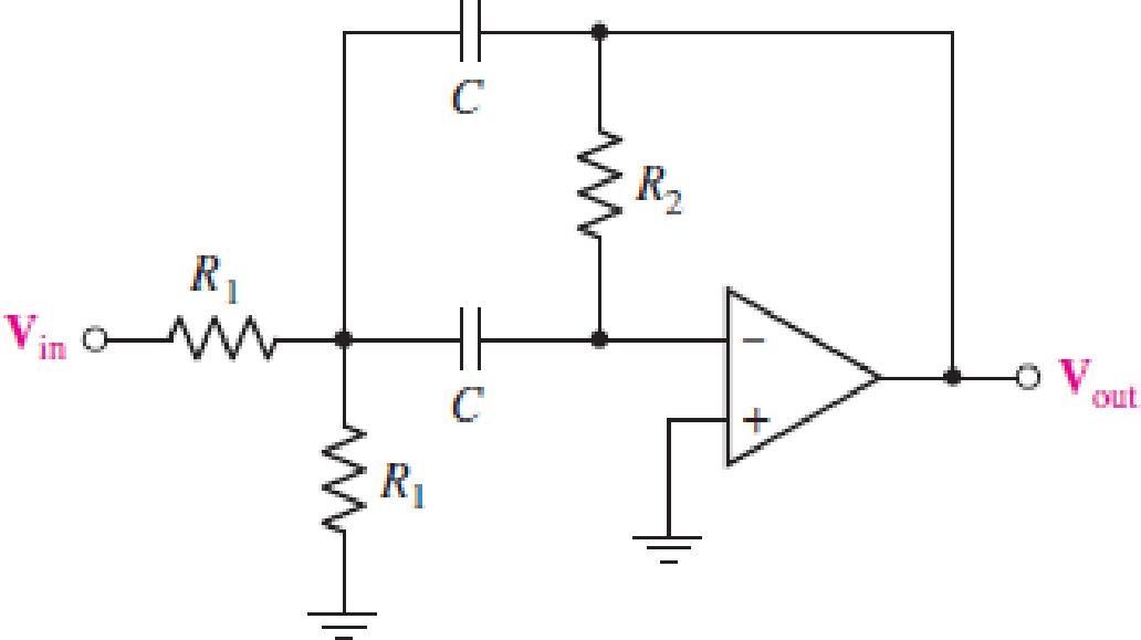
For the circuit in Fig. 15.56, (a) determine the transfer function H(jω) = Vout/Vin in terms of circuit parameters R1, R2, and C; (b) determine the magnitude and phase of the transfer function at ω = 0, 3 × 10⁴ rad/s, and as ω → ∞ for the case where circuit values are R1 = 500 Ω, R2 = 40 kΩ, and C = 10 nF.
FIGURE 15.56
(a)
The transfer function
Answer to Problem 6E
The transfer function
Explanation of Solution
Given data:
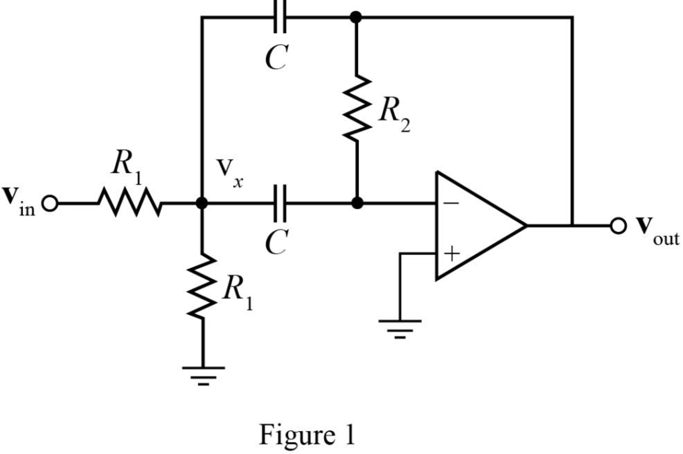
The required diagram is shown in Figure 1.
Calculation:
The equivalent impedance of the capacitor is given as,
The Kirchhoff’s current law equation at node
Here,
The Kirchhoff’s current law equation at
The transfer function
Substitute
Substitute
Conclusion:
Therefore, the transfer function
(b)
The magnitude of transfer function
Answer to Problem 6E
The magnitude of transfer function
Explanation of Solution
Given data:
The resistance
The resistance
The capacitor
The angular frequency
The angular frequency
The angular frequency
Calculation:
The conversion of
The conversion of
The conversion of
The conversion of
The magnitude of transfer function
The phase of transfer function
Substitute
Substitute
The magnitude of transfer function
The magnitude of transfer function
Substitute
Substitute
The magnitude of transfer function
The magnitude of transfer function
Substitute
Substitute
Conclusion:
Therefore, the magnitude of transfer function
Want to see more full solutions like this?
Chapter 15 Solutions
Loose Leaf for Engineering Circuit Analysis Format: Loose-leaf
Additional Engineering Textbook Solutions
Engineering Electromagnetics
ANALYSIS+DESIGN OF LINEAR CIRCUITS(LL)
Basic Engineering Circuit Analysis
Fundamentals of Electric Circuits
Principles and Applications of Electrical Engineering
ELECTRICITY FOR TRADES (LOOSELEAF)


- For the OP-Amp circuit below: a) Derive the transfer function, T(s). b) Calculate the magnitude of the filter. c) What is the order of this filter? d) What type of filter is this? e) Draw the S-Plane Singularities shown the radial distance from the origin. 8Ω V10 O v2 1/16 F 40arrow_forwardCan someone show me how to calculate magnitude and phase of the transfer function below Don't provide answer in handwritten way Only typed answere Oarrow_forward2. For the following circuit: a. Determine the transfer function H(jo) (Show all your work). b. Sketch |H(jo) | c. Calculate the center frequency, upper and lower cutoff frequencies d. Calculate and bandwidth in Hz. e. Find vo(t) for the input of vi(t) = 2 cos(2n3000t) Solution: V:(t) R1 w 1 ΚΩ L1 100 mH C1 H 0.1 μF 1 ΚΩ V.(t) fe₁, fcz in Hz.arrow_forward
- Q.3/ Find the difference equation that describe, the following digital filter: M (Z) E (2) 27²-3.52 +1.9 2²³²-2.77² +Z-0.95arrow_forwarda a llAsiacell A distorted signal of frequency fm is recovered from a sampled signal if the sampling frequency fs is: O fs = 2fm O fs 2fmarrow_forwardDerive and plot the magnitude and phase responses of the first order difference system, y[n] = x[n]–x[n − 1]. ..arrow_forward
- 1. A parallel R-L-C circuit is fed by a constant current source of variable frequency. The circuit resonates at 100 kHz and the Q-factor measured at this frequency is 5. Find the frequencies at which the amplitude of the voltage across the circuit falls to (a) 70.7% (b) 50% of the resonant frequency amplitude. [(a) 90.5 kHz ; 110.5 kHz (b) 84.18 kHz ; 118.8 kHz]arrow_forwardElectrical Engineering Design a low-pass, high-pass, and band-pass filter based on the following schematic selecting your own values for components. Analyse the circuits in frequency iden- tifying center and cut-off frequencies. Build and verify the operation of the circuit based on the designs. V_L+ VC+ V_Lref V Cref VR+ 10.0mH 5.0µF Vin R1 5V Vout 500HZ 10.00 V Rrefarrow_forwardPassive filters are made of passive components, tuned to the harmonic frequencies that are to be attenuated. Show that a series LR circuit is a lowpass filter if the output is taken across the resistor.arrow_forward
- 1 / 2 100% + Problem 3 Determine the input-output relationship, the system transfer function, and plot the pole-zero pattern for the discrete-time system shown below. rcos e rsin 0 rsin 0 x(n) -rsin e -rcos e 1-2 rcos earrow_forwardQuestion # 1 a) A certain filter has the following transfer function. 1500 H(jw)= (jw +50)² Find the value of frequency at which the magnitude equal (0.5 Hmax) b) The following circuit represents a filter 1- find he transfer function H(jw) Vo(jw)/Vs(jw). 2- find the kind of the filter, center frequency, cutoff frequencies and quality factor Vin(t) R2 R1 + Vo(t)arrow_forward3 9. The circuit is as shown in the figure, and the capacitance in the passband can be regarded as a short circuit. The gm of T1 is gm=1mS.Determine the voltage gain of the circuit Av=vo/vi= () VDD 20V R 10k Q C2 Re 300k Q 4.7 µF 0.02 µF Re 2M Q R Vo Re 100k 2 R 10k 2 47 uFarrow_forward
 Introductory Circuit Analysis (13th Edition)Electrical EngineeringISBN:9780133923605Author:Robert L. BoylestadPublisher:PEARSON
 Delmar's Standard Textbook Of ElectricityElectrical EngineeringISBN:9781337900348Author:Stephen L. HermanPublisher:Cengage Learning
 Programmable Logic ControllersElectrical EngineeringISBN:9780073373843Author:Frank D. PetruzellaPublisher:McGraw-Hill Education
 Fundamentals of Electric CircuitsElectrical EngineeringISBN:9780078028229Author:Charles K Alexander, Matthew SadikuPublisher:McGraw-Hill Education
 Electric Circuits. (11th Edition)Electrical EngineeringISBN:9780134746968Author:James W. Nilsson, Susan RiedelPublisher:PEARSON
 Engineering ElectromagneticsElectrical EngineeringISBN:9780078028151Author:Hayt, William H. (william Hart), Jr, BUCK, John A.Publisher:Mcgraw-hill Education,