
Loose Leaf for Engineering Circuit Analysis Format: Loose-leaf
9th Edition
ISBN: 9781259989452
Author: Hayt
Publisher: Mcgraw Hill Publishers
expand_more
expand_more
format_list_bulleted
Concept explainers
Videos
Textbook Question
Chapter 15, Problem 50E
Examine the filter for the circuit in Fig. 15.69. (a) Without going through a full mathematical analysis of the circuit, determine what kind of filter this is. (b) Determine an expression for the transfer function H(s) = vout/vin. (c) Use MATLAB to construct a Bode plot (with frequency in Hz) for R1 = R2 = 10 kΩ, C1 = 159 nF, C2 = 1.59 nF.
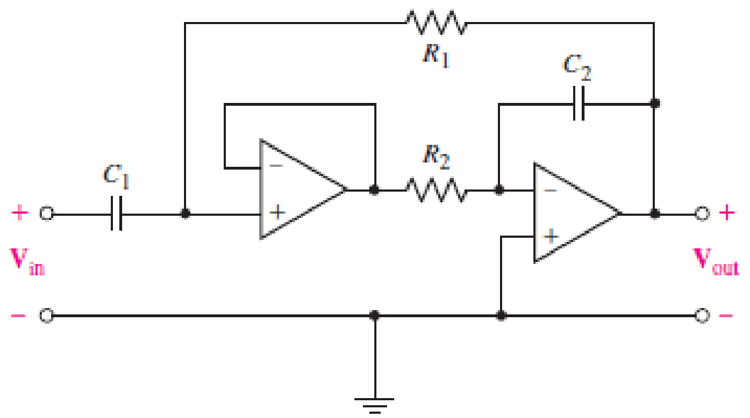
■ FIGURE 15.69
Expert Solution & Answer
Want to see the full answer?
Check out a sample textbook solution
Students have asked these similar questions
Hw. #I
R3
RI
using the
followiag
Rz Vi
circuit.
RL
O ) Derive the transfer
function Tis) = Vols)
V:(s)
b) what is the order of then filter?
c) what type of filter is this
VS+
-SA
V1
5
V2
5
.ac dec 100 1 1Meg
lib LM741.mod
VIN
V3
R1
C1
1.3k 0.12μ
AC 1
Figure. Active Band Pass Filter
R2
1.3k
C2
0.12μ
Imax
-VS+
-SA
U1
VOUT
LM741/NS
Provide the following expressions or values as required:
VOUT
VIN
) Expression for the maximum gain/magnitude G =
) Expression for the natural frequency fo and its corresponding value
) Expression for selectivity Q and its corresponding value
and its corresponding value
Figure 2 (High Pass Filter)
Figure 3 (Band-Pass Filter)
Please, Find the transfer functions of these two circuits and find their cutoff frequencies. calculate.
Chapter 15 Solutions
Loose Leaf for Engineering Circuit Analysis Format: Loose-leaf
Ch. 15.1 - Write an expression for the transfer function of...Ch. 15.2 - Calculate HdB at = 146 rad/s if H(s) equals (a)...Ch. 15.2 - Prob. 3PCh. 15.2 - Draw the Bode phase plot for the transfer function...Ch. 15.2 - Construct a Bode magnitude plot for H(s) equal to...Ch. 15.2 - Draw the Bode phase plot for H(s) equal to (a)...Ch. 15.2 - Prob. 7PCh. 15.3 - A parallel resonant circuit is composed of the...Ch. 15.3 - Prob. 9PCh. 15.4 - A marginally high-Q parallel resonant circuit has...
Ch. 15.5 - A series resonant circuit has a bandwidth of 100...Ch. 15.6 - Referring to the circuit of Fig. 15.25a, let R1 =...Ch. 15.6 - Prob. 13PCh. 15.6 - Prob. 14PCh. 15.6 - The series combination of 10 and 10 nF is in...Ch. 15.7 - A parallel resonant circuit is defined by C = 0.01...Ch. 15.8 - Design a high-pass filter with a cutoff frequency...Ch. 15.8 - Design a bandpass filter with a low-frequency...Ch. 15.8 - Design a low-pass filter circuit with a gain of 30...Ch. 15 - For the RL circuit in Fig. 15.52, (a) determine...Ch. 15 - For the RL circuit in Fig. 15.52, switch the...Ch. 15 - Examine the series RLC circuit in Fig. 15.53, with...Ch. 15 - For the circuit in Fig. 15.54, (a) derive an...Ch. 15 - For the circuit in Fig. 15.55, (a) derive an...Ch. 15 - For the circuit in Fig. 15.56, (a) determine the...Ch. 15 - For the circuit in Fig. 15.57, (a) determine the...Ch. 15 - Sketch the Bode magnitude and phase plots for the...Ch. 15 - Use the Bode approach to sketch the magnitude of...Ch. 15 - If a particular network is described by transfer...Ch. 15 - Use MATLAB to plot the magnitude and phase Bode...Ch. 15 - Determine the Bode magnitude plot for the...Ch. 15 - Determine the Bode magnitude and phase plot for...Ch. 15 - Prob. 15ECh. 15 - Prob. 16ECh. 15 - For the circuit of Fig. 15.56, construct a...Ch. 15 - Construct a magnitude and phase Bode plot for the...Ch. 15 - For the circuit in Fig. 15.54, use LTspice to...Ch. 15 - For the circuit in Fig. 15.55, use LTspice to...Ch. 15 - Prob. 21ECh. 15 - A certain parallel RLC circuit is built using...Ch. 15 - A parallel RLC network is constructed using R = 5...Ch. 15 - Prob. 24ECh. 15 - Delete the 2 resistor in the network of Fig....Ch. 15 - Delete the 1 resistor in the network of Fig....Ch. 15 - Prob. 28ECh. 15 - Prob. 29ECh. 15 - Prob. 30ECh. 15 - A parallel RLC network is constructed with a 200 H...Ch. 15 - Prob. 32ECh. 15 - A parallel RLC circuit is constructed such that it...Ch. 15 - Prob. 34ECh. 15 - Prob. 35ECh. 15 - An RLC circuit is constructed using R = 5 , L = 20...Ch. 15 - Prob. 37ECh. 15 - Prob. 38ECh. 15 - For the network of Fig. 15.25a, R1 = 100 , R2 =...Ch. 15 - Assuming an operating frequency of 200 rad/s, find...Ch. 15 - Prob. 41ECh. 15 - Prob. 42ECh. 15 - For the circuit shown in Fig. 15.64, the voltage...Ch. 15 - Prob. 44ECh. 15 - Prob. 45ECh. 15 - Prob. 46ECh. 15 - The filter shown in Fig. 15.66a has the response...Ch. 15 - Prob. 48ECh. 15 - Examine the filter for the circuit in Fig. 15.68....Ch. 15 - Examine the filter for the circuit in Fig. 15.69....Ch. 15 - (a)Design a high-pass filter with a corner...Ch. 15 - (a) Design a low-pass filter with a break...Ch. 15 - Prob. 53ECh. 15 - Prob. 54ECh. 15 - Design a low-pass filter characterized by a...Ch. 15 - Prob. 56ECh. 15 - The circuit in Fig. 15.70 is known as a notch...Ch. 15 - (a) Design a two-stage op amp filter circuit with...Ch. 15 - Design a circuit which removes the entire audio...Ch. 15 - Prob. 61ECh. 15 - If a high-pass filter is required having gain of 6...Ch. 15 - (a) Design a second-order high-pass Butterworth...Ch. 15 - Design a fourth-order high-pass Butterworth filter...Ch. 15 - (a) Design a Sallen-Key low-pass filter with a...Ch. 15 - (a) Design a Sallen-Key low-pass filter with a...Ch. 15 - A piezoelectric sensor has an equivalent circuit...Ch. 15 - Design a parallel resonant circuit for an AM radio...Ch. 15 - The network of Fig. 15.72 was implemented as a...Ch. 15 - Determine the effect of component tolerance on the...
Additional Engineering Textbook Solutions
Find more solutions based on key concepts
Find I0 and I1 in the circuit in Fig.P2.12.
Basic Engineering Circuit Analysis
Design an ideal inverting op-amp circuit such that the voltage gain is Av=25 . The maximum current in any resis...
Microelectronics: Circuit Analysis and Design
Assume a telephone signal travels through a cable at two-thirds the speed of light. How long does it take the s...
Electric Circuits (10th Edition)
Analog Voltmeter Design Figure P2-98(a) shows a voltmeter circuit consisting of a D'Arsonval meter, two series ...
ANALYSIS+DESIGN OF LINEAR CIRCUITS(LL)
Write the nodal equations for the network of Fig. 8.137 using the general approach. Find the nodal voltages usi...
Introductory Circuit Analysis (13th Edition)
When travelers from the USA and Canada visit Europe, they encounter a different power distribution system. Wall...
Electric machinery fundamentals
Knowledge Booster


Learn more about
Need a deep-dive on the concept behind this application? Look no further. Learn more about this topic, electrical-engineering and related others by exploring similar questions and additional content below.Similar questions
- Given the series RLC circuit. If R=10 ohm, find the values of L and C such that the network will have a center frequency of 100 kHz and a bandwidth of 1kHz. The output of the circuit is taken across series LC. Select one: O a. 1.59 mH and 1.59 nF O b. 1.59 mH and 1.59 uF 1.59 H and 1.59 nF 1.59 uH and 1.59 uF O C. O d.arrow_forwardO d. FM demodulator Choose the correct statement(s) that describe the diagram below. - x,(1) Bandpass filter Envelope detector Limiter Differentiator Select one or more: a. FM Demodulator b. Narrowband to wideband conversion OC. PM Demodulator Od. Linear PLL model e. FM Discriminator with bandpass limiter A third-order PLL can track a frequency-ramp with zero steady-state nhase errorarrow_forwardDetermine the voltage transfer function of the filter circuit shown below and classify the filter as LP, HP, BP or BS. Clearly explain your reasoning. R₁ R Vin A L voo outarrow_forward
- Given the series RLC circuit. If R=-10 ohm, find the values of L and C such that the network will have a center frequency of 100 kHz and a bandwidth of 1kHz. The output of the circuit is taken across series LC. Select one: O a. 1.59 mH and 1.59 nF O b. 1.59 mH and 1.59 uF Oc 1.59 uH and 1.59 uF O d. 1.59 H and 1.59 nFarrow_forwardI want the answer in detail and as quickly as possible please Q/ Using capacitors and resistors, design A - (band-pass filters) with Fl=108HZ and Fh=112HZ. B - Design (band-pass filters) with Fl = 218HZ and Fh = 223HZ. %3D ((And make sure that the values are available in the market))arrow_forwardPassive filters are made of passive components, tuned to the harmonic frequencies that are to be attenuated. Show that a series LR circuit is a lowpass filter if the output is taken across the resistor.arrow_forward
- 1. For the circuit in the figure below, obtain the transfer function output voltage / input voltage. Identify the type of filter and determine the corner frequency. Let R1=1000, R2=100N, and L=2mH. R1 L R2 v,(t) |(1)'a wwarrow_forwardDesign a series RLC bandpass filter as shown in the figure with lower cut-off frequency f = 400 Hz and bandwidth B = 9600 Hz %3D a) Determine the higher cut-off frequency f# b) Determine the center or resonant frequency fo in Hz and wo in rad/s and calculate the quality factor Q c) Choose C = 2 nF and find the values of R and L to meet the design specifications C No V: Oarrow_forward(c) Design a series RLC bandpass filter with cutoff frequencies fc₁ = 1 KHz, fcz = 20 KHz, using a 100 resistor. Draw the circuit and label all the components, including circuit values, including input and output. Also draw the magnitude and phase plots for the filter. Amplitude [dB] 50 40 30- Phase [°] 10 of- -10... -20... -30- -40- -50 0.1 180 135 90 C 45 of -45- -90 -135- -180 0.1 1 1 10 10 100 100 1000 1000 10,000 Freq. (Hz) 10,000 Freq. (Hz)arrow_forward
- Required information The circuit shown in the given figure is an active filter. Assume C=15 nF. Ro 4 kohm, R₁-1.2 kohm, R₂ =29.4 kohm, and R3=97.7 kohm. NOTE This is a multi-part question. Once an answer is submitted, you will be unable to return to this part. ww www R₁ C Determine the cutoff frequencies www 20 The cutoff frequencies w₁ and 2 are X 103 and 104, 4, respectively.arrow_forwardDesign an active lowpass filter with dc gain of 0.5 and corner frequency of 250Hz. Then draw the circuit diagram for this filter.arrow_forwardI need some help. I am designing a bandpass filter with fl=3400 Hz and fh= 7500 Hz. Based on that I need the values for the RCL circuit, assuming that the capacitor is 1 microfarat. So, I need some help in calculate the center frequency, bandwith, Q, center frequency as well. I need clear steps and calculations. Any help will be appretiated.arrow_forward
arrow_back_ios
SEE MORE QUESTIONS
arrow_forward_ios
Recommended textbooks for you
 Introductory Circuit Analysis (13th Edition)Electrical EngineeringISBN:9780133923605Author:Robert L. BoylestadPublisher:PEARSON
 Delmar's Standard Textbook Of ElectricityElectrical EngineeringISBN:9781337900348Author:Stephen L. HermanPublisher:Cengage Learning
 Programmable Logic ControllersElectrical EngineeringISBN:9780073373843Author:Frank D. PetruzellaPublisher:McGraw-Hill Education
 Fundamentals of Electric CircuitsElectrical EngineeringISBN:9780078028229Author:Charles K Alexander, Matthew SadikuPublisher:McGraw-Hill Education
 Electric Circuits. (11th Edition)Electrical EngineeringISBN:9780134746968Author:James W. Nilsson, Susan RiedelPublisher:PEARSON
 Engineering ElectromagneticsElectrical EngineeringISBN:9780078028151Author:Hayt, William H. (william Hart), Jr, BUCK, John A.Publisher:Mcgraw-hill Education,
Introductory Circuit Analysis (13th Edition)
Electrical Engineering
ISBN:9780133923605
Author:Robert L. Boylestad
Publisher:PEARSON
Delmar's Standard Textbook Of Electricity
Electrical Engineering
ISBN:9781337900348
Author:Stephen L. Herman
Publisher:Cengage Learning
Programmable Logic Controllers
Electrical Engineering
ISBN:9780073373843
Author:Frank D. Petruzella
Publisher:McGraw-Hill Education
Fundamentals of Electric Circuits
Electrical Engineering
ISBN:9780078028229
Author:Charles K Alexander, Matthew Sadiku
Publisher:McGraw-Hill Education
Electric Circuits. (11th Edition)
Electrical Engineering
ISBN:9780134746968
Author:James W. Nilsson, Susan Riedel
Publisher:PEARSON
Engineering Electromagnetics
Electrical Engineering
ISBN:9780078028151
Author:Hayt, William H. (william Hart), Jr, BUCK, John A.
Publisher:Mcgraw-hill Education,
What is Filter & Classification of Filters | Four Types of Filters | Electronic Devices & Circuits; Author: SimplyInfo;https://www.youtube.com/watch?v=9x1Sjz-VPSg;License: Standard Youtube License