
Loose Leaf for Engineering Circuit Analysis Format: Loose-leaf
9th Edition
ISBN: 9781259989452
Author: Hayt
Publisher: Mcgraw Hill Publishers
expand_more
expand_more
format_list_bulleted
Concept explainers
Videos
Textbook Question
Chapter 7, Problem 37E
Reduce the circuit depicted in Fig. 7.59 to as few components as possible, noting that the voltage vx is important.
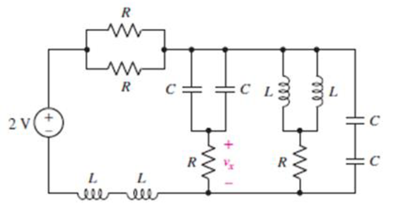
FIGURE 7.59
Expert Solution & Answer
Want to see the full answer?
Check out a sample textbook solution
Students have asked these similar questions
7.7μF capacitor is charged by a 125V battery and then is disconnected from the battery. When this capacitor (C1) is then connected to a second (initially uncharged) capacitor, C2, the final voltage on each capacitor is 15V. What is the value of C2? [Hint: Charge is conserved.]
A dc constant voltage source feeds a resistance of 2,000 kΩ in series with a 5µF capacitor. Find the time taken for the capacitor when the charge retained will be decayed to 50% of the initial value, the voltage sourcing being short circuited.
Ans 11
Give reason :
a) The total resistance in a circuit with parallel resistors increases , if one of the parallel resistors opens .
b) If the inductor is charged it acts as an open circuit.
c) If the capacitor is fully discharged it acts as a short circuit .
Chapter 7 Solutions
Loose Leaf for Engineering Circuit Analysis Format: Loose-leaf
Ch. 7.1 - Determine the current flowing through a 5 mF...Ch. 7.1 - Prob. 2PCh. 7.1 - Prob. 3PCh. 7.2 - 7.4 The current through a 200 mH inductor is shown...Ch. 7.2 - The current waveform of Fig. 7.14a has equal rise...Ch. 7.2 - Prob. 6PCh. 7.2 - Let L = 25 mH for the inductor of Fig. 7.10. (a)...Ch. 7.3 - Find Ceq for the network of Fig. 7.23. FIGURE...Ch. 7.4 - If vC(t) = 4 cos 105t V in the circuit in Fig....Ch. 7.5 - Derive an expression for vout in terms of vs for...
Ch. 7.6 - Prob. 11PCh. 7 - Making use of the passive sign convention,...Ch. 7 - Prob. 2ECh. 7 - (a) If the voltage waveform depicted in Fig. 7.42...Ch. 7 - A capacitor is constructed from two brass plates,...Ch. 7 - Prob. 5ECh. 7 - Prob. 6ECh. 7 - Design a capacitor whose capacitance can be varied...Ch. 7 - Design a capacitor whose capacitance can be varied...Ch. 7 - Prob. 9ECh. 7 - Assuming the passive sign convention, sketch the...Ch. 7 - Prob. 11ECh. 7 - Prob. 12ECh. 7 - Prob. 13ECh. 7 - Calculate the power dissipated in the 40 resistor...Ch. 7 - Prob. 15ECh. 7 - Design a 30 nH inductor using 28 AWG solid soft...Ch. 7 - Prob. 17ECh. 7 - Prob. 18ECh. 7 - Prob. 19ECh. 7 - Prob. 20ECh. 7 - Calculate vL and iL for each of the circuits...Ch. 7 - The current waveform shown in Fig. 7.14 has a rise...Ch. 7 - Determine the inductor voltage which results from...Ch. 7 - Prob. 24ECh. 7 - The voltage across a 2 H inductor is given by vL =...Ch. 7 - Calculate the energy stored in a 1 nH inductor if...Ch. 7 - Determine the amount of energy stored in a 33 mH...Ch. 7 - Making the assumption that the circuits in Fig....Ch. 7 - Calculate the voltage labeled vx in Fig. 7.52,...Ch. 7 - Prob. 30ECh. 7 - Prob. 31ECh. 7 - Determine an equivalent inductance for the network...Ch. 7 - Using as many 1 nH inductors as you like, design...Ch. 7 - Compute the equivalent capacitance Ceq as labeled...Ch. 7 - Prob. 35ECh. 7 - Prob. 36ECh. 7 - Reduce the circuit depicted in Fig. 7.59 to as few...Ch. 7 - Refer to the network shown in Fig. 7.60 and find...Ch. 7 - Prob. 39ECh. 7 - Prob. 40ECh. 7 - Prob. 41ECh. 7 - Prob. 42ECh. 7 - Prob. 43ECh. 7 - Prob. 44ECh. 7 - Prob. 45ECh. 7 - Prob. 46ECh. 7 - Prob. 47ECh. 7 - Let vs = 100e80t V with no initial energy stored...Ch. 7 - Prob. 49ECh. 7 - Prob. 50ECh. 7 - Interchange the location of R1 and Cf in the...Ch. 7 - For the integrating amplifier circuit of Fig....Ch. 7 - Prob. 53ECh. 7 - For the circuit shown in Fig. 7.73, assume no...Ch. 7 - A new piece of equipment designed to make crystals...Ch. 7 - An altitude sensor on a weather balloon provides a...Ch. 7 - One problem satellites face is exposure to...Ch. 7 - The output of a velocity sensor attached to a...Ch. 7 - A floating sensor in a certain fuel tank is...Ch. 7 - (a) If Is = 3 sin t A, draw the exact dual of the...Ch. 7 - Draw the exact dual of the simple circuit shown in...Ch. 7 - (a) Draw the exact dual of the simple circuit...Ch. 7 - (a) Draw the exact dual of the simple circuit...Ch. 7 - Prob. 64ECh. 7 - Prob. 65ECh. 7 - Prob. 66ECh. 7 - Prob. 67ECh. 7 - Prob. 68ECh. 7 - Prob. 69ECh. 7 - Prob. 70ECh. 7 - For the circuit of Fig. 7.28, (a) sketch vout over...Ch. 7 - (a) Sketch the output function vout of the...Ch. 7 - For the circuit of Fig. 7.72, (a) sketch vout over...
Knowledge Booster


Learn more about
Need a deep-dive on the concept behind this application? Look no further. Learn more about this topic, electrical-engineering and related others by exploring similar questions and additional content below.Similar questions
- Example 2. Find the equivalent capacitance seen at the terminals of the circuit in Figure 7. 50 μF Ceg 70 F Figure 7. Ans. 40uF 60 μF 20 μF 120 μFarrow_forwardA voltage of .... appears between the terminals of a combination of a 100 mF capacitor and a 12 oms resistor in parallel. Calculate the power absorbed by the parallel combination. Note: I leave the image of the exercises in Spanish, but it is easy to understand. Also in the other image is the correct final answer, for checking.arrow_forwardFind the time constant for each of the circuits in Fig. 7.95. 48 Ω 160 2 40 Ω 20 mAns: wwarrow_forward
- a resistance of 100k ohms is connected in series with a 100uF capacitor.if the combination is suddenly connected across a 125V DC source, determine the current one second after the switch is closedarrow_forwardCalculate v₁ and it for each of the circuits depicted in Fig. 7.48, if is = 1 mA and vs 2.1 V. = Vs is + 4.7 ΚΩ M (a) 4.7 ΚΩ. (c) 12 nH iL 12 nH VL is Vs + 4.7 ΚΩ 14 ΚΩ M (b) 4.7 ΚΩ (d) iL 12 nH iL m +51 12 nH 14 ΚΩ ww VL ell +51 VLarrow_forwardA certain solar cell type has an output capability of 9.2 A at 0.7 V. A series / parallel solar array has been designed of such cells with 11 parallel strings and each string has 114 cells in series. Calculate Voltage capability of array.arrow_forward
- Reduce the circuit depicted in Fig. 7.58 to as few components as possible. 2 V + R W ww R R M FIGURE 7.58 с R + Vx CL ell R мее L Carrow_forward1-A Pacemaker is a device that is implanted in the body and it helps to control the heartbeat by preventing the heart from beating too slowly. A pacemaker that is connected to a battery with a voltage of 9.0 V and has a capacitor with a capacitance of 110 µF is designed to deliver 5 pulses every 4 seconds. The pacemaker will deliver a pulse to the patients body every time its' capacitor is charged to 0.25 V. What resistance should the pacemaker have to achieve the desired pulse delivery (5 pulse every 4 second). 2-For the circuit below find the current in each resistor using the kirchoff method ww 3.9 1 12 V 1.20 9.8 Ω A ww 6.70 9.0 V Barrow_forwardA capacitor that is initially uncharged is connected in series with a resistor and a 300.0 V emf source with negligible internal resistance. Just after the circuit is completed, the current through the resistor is 0.950 mA and the time constant for the circuit is 6.00 s. (A) What is the resistance of the resistor? (B) What is the capacitance of the capacitor?arrow_forward
- electric circuit analysis electric circuit fundamentals by franco chapter 7 problem 7.35arrow_forwardQuestion 11 The current flowing through a 33 mF capacitor is shown graphically in Fig. 7.43. a) Assuming the passive sign convention, sketch the resulting voltage waveform across the device. b) Compute the voltage at 300 ms, 600 ms, and 1.1 s. i(A) 8 4 0 0.2 0.4 0.6 0.8 1.0 1.2 1.4 FIGURE 7.43 1 (S)arrow_forwardProblem 1 (time constant in RC Circuits, Alexander 7.2) 120 Ω 12Ω ww 50 V (+ 80 Ω 200 mF Figure P1 Find the time constant for the RC circuit in Figure P1. wwarrow_forward
arrow_back_ios
SEE MORE QUESTIONS
arrow_forward_ios
Recommended textbooks for you
 Introductory Circuit Analysis (13th Edition)Electrical EngineeringISBN:9780133923605Author:Robert L. BoylestadPublisher:PEARSON
 Delmar's Standard Textbook Of ElectricityElectrical EngineeringISBN:9781337900348Author:Stephen L. HermanPublisher:Cengage Learning
 Programmable Logic ControllersElectrical EngineeringISBN:9780073373843Author:Frank D. PetruzellaPublisher:McGraw-Hill Education
 Fundamentals of Electric CircuitsElectrical EngineeringISBN:9780078028229Author:Charles K Alexander, Matthew SadikuPublisher:McGraw-Hill Education
 Electric Circuits. (11th Edition)Electrical EngineeringISBN:9780134746968Author:James W. Nilsson, Susan RiedelPublisher:PEARSON
 Engineering ElectromagneticsElectrical EngineeringISBN:9780078028151Author:Hayt, William H. (william Hart), Jr, BUCK, John A.Publisher:Mcgraw-hill Education,
Introductory Circuit Analysis (13th Edition)
Electrical Engineering
ISBN:9780133923605
Author:Robert L. Boylestad
Publisher:PEARSON
Delmar's Standard Textbook Of Electricity
Electrical Engineering
ISBN:9781337900348
Author:Stephen L. Herman
Publisher:Cengage Learning
Programmable Logic Controllers
Electrical Engineering
ISBN:9780073373843
Author:Frank D. Petruzella
Publisher:McGraw-Hill Education
Fundamentals of Electric Circuits
Electrical Engineering
ISBN:9780078028229
Author:Charles K Alexander, Matthew Sadiku
Publisher:McGraw-Hill Education
Electric Circuits. (11th Edition)
Electrical Engineering
ISBN:9780134746968
Author:James W. Nilsson, Susan Riedel
Publisher:PEARSON
Engineering Electromagnetics
Electrical Engineering
ISBN:9780078028151
Author:Hayt, William H. (william Hart), Jr, BUCK, John A.
Publisher:Mcgraw-hill Education,
ENA 9.2(1)(En)(Alex) Sinusoids & Phasors - Explanation with Example 9.1 ,9.2 & PP 9.2; Author: Electrical Engineering Academy;https://www.youtube.com/watch?v=vX_LLNl-ZpU;License: Standard YouTube License, CC-BY
Electrical Engineering: Ch 10 Alternating Voltages & Phasors (8 of 82) What is a Phasor?; Author: Michel van Biezen;https://www.youtube.com/watch?v=2I1tF3ixNg0;License: Standard Youtube License