
Loose Leaf for Engineering Circuit Analysis Format: Loose-leaf
9th Edition
ISBN: 9781259989452
Author: Hayt
Publisher: Mcgraw Hill Publishers
expand_more
expand_more
format_list_bulleted
Concept explainers
Videos
Textbook Question
Chapter 7, Problem 52E
For the integrating amplifier circuit of Fig. 7.27, R1 = 100 kΩ, Cf = 500 μF, and vs = 20 sin 540t mV. Calculate vout.
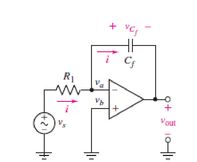
FIGURE 7.27 An ideal op amp connected as an integrator.
Expert Solution & Answer
Want to see the full answer?
Check out a sample textbook solution
Students have asked these similar questions
OP-AMP Review questions
(7.2) If the values of the resistors are given as: R1= 27KN, R2= 82KN, R3= 10K2, R4= 12KN, R5=
39KN, R6= 56 KN, Find the expression for the output voltage in terms of Vx, Vy, Vz. For better
accuracy of the answers, use 4 decimal places.
R,
R
R6
An op amp has Vsat = +/- 13 V, SR = 1.7 V/μs, and is used as a comparator. What is the approximate time it takes to transition from one output state to the other?
.l Asiacell LTE
e 7:09 PM
O 60%
2.pdf
Using inverting, non-inverting, Buffer, or Summer op_amps circuit to
design the following equation
Vo = 8 Vị
Chapter 7 Solutions
Loose Leaf for Engineering Circuit Analysis Format: Loose-leaf
Ch. 7.1 - Determine the current flowing through a 5 mF...Ch. 7.1 - Prob. 2PCh. 7.1 - Prob. 3PCh. 7.2 - 7.4 The current through a 200 mH inductor is shown...Ch. 7.2 - The current waveform of Fig. 7.14a has equal rise...Ch. 7.2 - Prob. 6PCh. 7.2 - Let L = 25 mH for the inductor of Fig. 7.10. (a)...Ch. 7.3 - Find Ceq for the network of Fig. 7.23. FIGURE...Ch. 7.4 - If vC(t) = 4 cos 105t V in the circuit in Fig....Ch. 7.5 - Derive an expression for vout in terms of vs for...
Ch. 7.6 - Prob. 11PCh. 7 - Making use of the passive sign convention,...Ch. 7 - Prob. 2ECh. 7 - (a) If the voltage waveform depicted in Fig. 7.42...Ch. 7 - A capacitor is constructed from two brass plates,...Ch. 7 - Prob. 5ECh. 7 - Prob. 6ECh. 7 - Design a capacitor whose capacitance can be varied...Ch. 7 - Design a capacitor whose capacitance can be varied...Ch. 7 - Prob. 9ECh. 7 - Assuming the passive sign convention, sketch the...Ch. 7 - Prob. 11ECh. 7 - Prob. 12ECh. 7 - Prob. 13ECh. 7 - Calculate the power dissipated in the 40 resistor...Ch. 7 - Prob. 15ECh. 7 - Design a 30 nH inductor using 28 AWG solid soft...Ch. 7 - Prob. 17ECh. 7 - Prob. 18ECh. 7 - Prob. 19ECh. 7 - Prob. 20ECh. 7 - Calculate vL and iL for each of the circuits...Ch. 7 - The current waveform shown in Fig. 7.14 has a rise...Ch. 7 - Determine the inductor voltage which results from...Ch. 7 - Prob. 24ECh. 7 - The voltage across a 2 H inductor is given by vL =...Ch. 7 - Calculate the energy stored in a 1 nH inductor if...Ch. 7 - Determine the amount of energy stored in a 33 mH...Ch. 7 - Making the assumption that the circuits in Fig....Ch. 7 - Calculate the voltage labeled vx in Fig. 7.52,...Ch. 7 - Prob. 30ECh. 7 - Prob. 31ECh. 7 - Determine an equivalent inductance for the network...Ch. 7 - Using as many 1 nH inductors as you like, design...Ch. 7 - Compute the equivalent capacitance Ceq as labeled...Ch. 7 - Prob. 35ECh. 7 - Prob. 36ECh. 7 - Reduce the circuit depicted in Fig. 7.59 to as few...Ch. 7 - Refer to the network shown in Fig. 7.60 and find...Ch. 7 - Prob. 39ECh. 7 - Prob. 40ECh. 7 - Prob. 41ECh. 7 - Prob. 42ECh. 7 - Prob. 43ECh. 7 - Prob. 44ECh. 7 - Prob. 45ECh. 7 - Prob. 46ECh. 7 - Prob. 47ECh. 7 - Let vs = 100e80t V with no initial energy stored...Ch. 7 - Prob. 49ECh. 7 - Prob. 50ECh. 7 - Interchange the location of R1 and Cf in the...Ch. 7 - For the integrating amplifier circuit of Fig....Ch. 7 - Prob. 53ECh. 7 - For the circuit shown in Fig. 7.73, assume no...Ch. 7 - A new piece of equipment designed to make crystals...Ch. 7 - An altitude sensor on a weather balloon provides a...Ch. 7 - One problem satellites face is exposure to...Ch. 7 - The output of a velocity sensor attached to a...Ch. 7 - A floating sensor in a certain fuel tank is...Ch. 7 - (a) If Is = 3 sin t A, draw the exact dual of the...Ch. 7 - Draw the exact dual of the simple circuit shown in...Ch. 7 - (a) Draw the exact dual of the simple circuit...Ch. 7 - (a) Draw the exact dual of the simple circuit...Ch. 7 - Prob. 64ECh. 7 - Prob. 65ECh. 7 - Prob. 66ECh. 7 - Prob. 67ECh. 7 - Prob. 68ECh. 7 - Prob. 69ECh. 7 - Prob. 70ECh. 7 - For the circuit of Fig. 7.28, (a) sketch vout over...Ch. 7 - (a) Sketch the output function vout of the...Ch. 7 - For the circuit of Fig. 7.72, (a) sketch vout over...
Knowledge Booster


Learn more about
Need a deep-dive on the concept behind this application? Look no further. Learn more about this topic, electrical-engineering and related others by exploring similar questions and additional content below.Similar questions
- Design a difference amplifier with gain 7.5arrow_forwardFind the output of the ideal operational amplifier shown in Figure 7-28 (p. 332) for each of the following input signals: (a) vi = 120 mV dc (b) vi = 0.5 sin ωt V.arrow_forwardTo increase the 75 V battery voltage to 100 V, a da-da circuit is required is heard. The converter inductance is 200 μH and the load resistance is 2.2 Ω.Powerswitch has a transmission time of 50 μs and operates in continuous transmission. According to this; d) Find the average value of the input current and the output current. e) Find the minimum and maximum values of the input current. f) Output to be used to limit the fluctuation in the input voltage to 10% of the output voltage.Find the capacity of the circuit.arrow_forward
- I. Design a suitable op amp circuit to implement the following equation: dv. f = 6(2V, – 4V2) – 3 V, + 2- dt II. An op amp has a GBP of 10°. A 0.8 uV sinusoidal signal at 10 KHz is required to be amplified to 5 V. Calculate the gains and draw the schematic circuit to achieve this.arrow_forwardThe op amp in the circuit shown is ideal. Suppose va=2 V. What value of Rf will cause the op amp to saturate?arrow_forwardC. None of these O d. 7.566 kO Assume Is = 8 × 10 A, B= 100, V= 26mV and VA =D0 For the circuit shown below and for h= 1.5 mA, the value of the transconductance is Vcc=D2 V Select one: O a 115 38mA/V Cb.19.23 mAN Oc 57 69 mAN Od.86.92 mA/V Oe. None of these In the transistor shown below choose the correct term.nalinames EN 2 1:48 AM 4/16/2021arrow_forward
- design and Draw the circuit of op-amp monostable multivibrator with fo= 200KHz and duty cycle of 40%arrow_forward5. Design an op-amp Voltmeter circuit which can measure a maximum input of 20 mV The op-amp input current is 0.2 µA, and the meter circuit has Im= 100 µA FSD and Rm=10kQ. Determine suitable resistance values for Ra and Rarrow_forward1. Design a suitable op amp circuit to implement the following equation: f = 2(V, - 5v,) + 6 v IL. Derive the characteristic equation of an accelerometer then show how can be used as a seismometer.arrow_forward
- A "RL circuit" with 18ohm resistor and a 0.30 Henry inductor. If it has an initial current of 1 amp, what would the current will be after 0.017 sec?arrow_forward(a) Write an expression for the output of the amplifier in Figure 7-32 (p. 334) in terms of v1, v2, v3, and v4. (b) What is the output when v1 = 5 sinωt, v2 = –3 V dc, v3 = –sin ωt, and v4 = 2 V dc? (c) What value should Rc have?arrow_forwardA three-phase full-wave half-controlled converter supplies a highly inductive load with R = 102 the supply is a three- phase star connected with 400 V RMS. The value of firing angle in degrees, to obtain the dc output current as 15 A isarrow_forward
arrow_back_ios
SEE MORE QUESTIONS
arrow_forward_ios
Recommended textbooks for you
 Introductory Circuit Analysis (13th Edition)Electrical EngineeringISBN:9780133923605Author:Robert L. BoylestadPublisher:PEARSON
 Delmar's Standard Textbook Of ElectricityElectrical EngineeringISBN:9781337900348Author:Stephen L. HermanPublisher:Cengage Learning
 Programmable Logic ControllersElectrical EngineeringISBN:9780073373843Author:Frank D. PetruzellaPublisher:McGraw-Hill Education
 Fundamentals of Electric CircuitsElectrical EngineeringISBN:9780078028229Author:Charles K Alexander, Matthew SadikuPublisher:McGraw-Hill Education
 Electric Circuits. (11th Edition)Electrical EngineeringISBN:9780134746968Author:James W. Nilsson, Susan RiedelPublisher:PEARSON
 Engineering ElectromagneticsElectrical EngineeringISBN:9780078028151Author:Hayt, William H. (william Hart), Jr, BUCK, John A.Publisher:Mcgraw-hill Education,
Introductory Circuit Analysis (13th Edition)
Electrical Engineering
ISBN:9780133923605
Author:Robert L. Boylestad
Publisher:PEARSON
Delmar's Standard Textbook Of Electricity
Electrical Engineering
ISBN:9781337900348
Author:Stephen L. Herman
Publisher:Cengage Learning
Programmable Logic Controllers
Electrical Engineering
ISBN:9780073373843
Author:Frank D. Petruzella
Publisher:McGraw-Hill Education
Fundamentals of Electric Circuits
Electrical Engineering
ISBN:9780078028229
Author:Charles K Alexander, Matthew Sadiku
Publisher:McGraw-Hill Education
Electric Circuits. (11th Edition)
Electrical Engineering
ISBN:9780134746968
Author:James W. Nilsson, Susan Riedel
Publisher:PEARSON
Engineering Electromagnetics
Electrical Engineering
ISBN:9780078028151
Author:Hayt, William H. (william Hart), Jr, BUCK, John A.
Publisher:Mcgraw-hill Education,
ENA 9.2(1)(En)(Alex) Sinusoids & Phasors - Explanation with Example 9.1 ,9.2 & PP 9.2; Author: Electrical Engineering Academy;https://www.youtube.com/watch?v=vX_LLNl-ZpU;License: Standard YouTube License, CC-BY
Electrical Engineering: Ch 10 Alternating Voltages & Phasors (8 of 82) What is a Phasor?; Author: Michel van Biezen;https://www.youtube.com/watch?v=2I1tF3ixNg0;License: Standard Youtube License