
Loose Leaf for Engineering Circuit Analysis Format: Loose-leaf
9th Edition
ISBN: 9781259989452
Author: Hayt
Publisher: Mcgraw Hill Publishers
expand_more
expand_more
format_list_bulleted
Concept explainers
Videos
Textbook Question
Chapter 7, Problem 38E
Refer to the network shown in Fig. 7.60 and find (a) Req if each element is a 10 Ω resistor; (b) Leq if each element is a 10 H inductor; and (c) Ceq if each element is a 10 F capacitor.
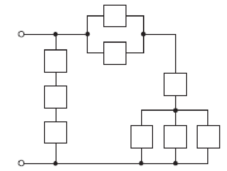
FIGURE 7.60
Expert Solution & Answer
Want to see the full answer?
Check out a sample textbook solution
Students have asked these similar questions
The R-L Circuit: An inductor with an inductance of 2.50 H and a resistance of 7.00 n is connected to the terminals ofa battery with an emf of 6.00 V and an internal resistance of 1.00 n. What is the rate ofincrease of current at the instant when the current is 0.500 A? A) 0.8 A/s B) 0.6 A/s C) 0.4 A/s D) zero E) None of the above.
The circuit below shows the typical arrangement of a camera flash.
The time taken for the capacitor to become fully charged
The initial rate of discharge of voltage across the 7Ω resistor.
A dc constant voltage source feeds a resistance of 2,000 kΩ in series with a 5µF capacitor. Find the time taken for the capacitor when the charge retained will be decayed to 50% of the initial value, the voltage sourcing being short circuited.
Ans 11
Chapter 7 Solutions
Loose Leaf for Engineering Circuit Analysis Format: Loose-leaf
Ch. 7.1 - Determine the current flowing through a 5 mF...Ch. 7.1 - Prob. 2PCh. 7.1 - Prob. 3PCh. 7.2 - 7.4 The current through a 200 mH inductor is shown...Ch. 7.2 - The current waveform of Fig. 7.14a has equal rise...Ch. 7.2 - Prob. 6PCh. 7.2 - Let L = 25 mH for the inductor of Fig. 7.10. (a)...Ch. 7.3 - Find Ceq for the network of Fig. 7.23. FIGURE...Ch. 7.4 - If vC(t) = 4 cos 105t V in the circuit in Fig....Ch. 7.5 - Derive an expression for vout in terms of vs for...
Ch. 7.6 - Prob. 11PCh. 7 - Making use of the passive sign convention,...Ch. 7 - Prob. 2ECh. 7 - (a) If the voltage waveform depicted in Fig. 7.42...Ch. 7 - A capacitor is constructed from two brass plates,...Ch. 7 - Prob. 5ECh. 7 - Prob. 6ECh. 7 - Design a capacitor whose capacitance can be varied...Ch. 7 - Design a capacitor whose capacitance can be varied...Ch. 7 - Prob. 9ECh. 7 - Assuming the passive sign convention, sketch the...Ch. 7 - Prob. 11ECh. 7 - Prob. 12ECh. 7 - Prob. 13ECh. 7 - Calculate the power dissipated in the 40 resistor...Ch. 7 - Prob. 15ECh. 7 - Design a 30 nH inductor using 28 AWG solid soft...Ch. 7 - Prob. 17ECh. 7 - Prob. 18ECh. 7 - Prob. 19ECh. 7 - Prob. 20ECh. 7 - Calculate vL and iL for each of the circuits...Ch. 7 - The current waveform shown in Fig. 7.14 has a rise...Ch. 7 - Determine the inductor voltage which results from...Ch. 7 - Prob. 24ECh. 7 - The voltage across a 2 H inductor is given by vL =...Ch. 7 - Calculate the energy stored in a 1 nH inductor if...Ch. 7 - Determine the amount of energy stored in a 33 mH...Ch. 7 - Making the assumption that the circuits in Fig....Ch. 7 - Calculate the voltage labeled vx in Fig. 7.52,...Ch. 7 - Prob. 30ECh. 7 - Prob. 31ECh. 7 - Determine an equivalent inductance for the network...Ch. 7 - Using as many 1 nH inductors as you like, design...Ch. 7 - Compute the equivalent capacitance Ceq as labeled...Ch. 7 - Prob. 35ECh. 7 - Prob. 36ECh. 7 - Reduce the circuit depicted in Fig. 7.59 to as few...Ch. 7 - Refer to the network shown in Fig. 7.60 and find...Ch. 7 - Prob. 39ECh. 7 - Prob. 40ECh. 7 - Prob. 41ECh. 7 - Prob. 42ECh. 7 - Prob. 43ECh. 7 - Prob. 44ECh. 7 - Prob. 45ECh. 7 - Prob. 46ECh. 7 - Prob. 47ECh. 7 - Let vs = 100e80t V with no initial energy stored...Ch. 7 - Prob. 49ECh. 7 - Prob. 50ECh. 7 - Interchange the location of R1 and Cf in the...Ch. 7 - For the integrating amplifier circuit of Fig....Ch. 7 - Prob. 53ECh. 7 - For the circuit shown in Fig. 7.73, assume no...Ch. 7 - A new piece of equipment designed to make crystals...Ch. 7 - An altitude sensor on a weather balloon provides a...Ch. 7 - One problem satellites face is exposure to...Ch. 7 - The output of a velocity sensor attached to a...Ch. 7 - A floating sensor in a certain fuel tank is...Ch. 7 - (a) If Is = 3 sin t A, draw the exact dual of the...Ch. 7 - Draw the exact dual of the simple circuit shown in...Ch. 7 - (a) Draw the exact dual of the simple circuit...Ch. 7 - (a) Draw the exact dual of the simple circuit...Ch. 7 - Prob. 64ECh. 7 - Prob. 65ECh. 7 - Prob. 66ECh. 7 - Prob. 67ECh. 7 - Prob. 68ECh. 7 - Prob. 69ECh. 7 - Prob. 70ECh. 7 - For the circuit of Fig. 7.28, (a) sketch vout over...Ch. 7 - (a) Sketch the output function vout of the...Ch. 7 - For the circuit of Fig. 7.72, (a) sketch vout over...
Knowledge Booster


Learn more about
Need a deep-dive on the concept behind this application? Look no further. Learn more about this topic, electrical-engineering and related others by exploring similar questions and additional content below.Similar questions
- Determine the current 7(1) in an RLC-circuit with resistance R = 802, %3D inductance L = 10 H ¸ capacitance C = 0.004 F and voltage E = 240.5 sin 10t V. %3Darrow_forwardGive reason : a) The total resistance in a circuit with parallel resistors increases , if one of the parallel resistors opens . b) If the inductor is charged it acts as an open circuit. c) If the capacitor is fully discharged it acts as a short circuit .arrow_forwardA 767 uF capacitor has an initial voltage, v(0) = 2 V. If the current flowing through the capacitor is i(t) = 11 mA, what is the voltage v(t) across the capacitor, at time t= 40ms? Enter your answer to 3 significant figures.arrow_forward
- 1-A Pacemaker is a device that is implanted in the body and it helps to control the heartbeat by preventing the heart from beating too slowly. A pacemaker that is connected to a battery with a voltage of 9.0 V and has a capacitor with a capacitance of 110 µF is designed to deliver 5 pulses every 4 seconds. The pacemaker will deliver a pulse to the patients body every time its' capacitor is charged to 0.25 V. What resistance should the pacemaker have to achieve the desired pulse delivery (5 pulse every 4 second). 2-For the circuit below find the current in each resistor using the kirchoff method ww 3.9 1 12 V 1.20 9.8 Ω A ww 6.70 9.0 V Barrow_forward1. A cardiac defibrillator is used to shock a heart that is beating erratically. The capacitor is charged to 6.0kV in this device and stores 1800J of energy. What is the capacitance?arrow_forwardb) What is the current at t = 0.008 s? (In [A]) c) What is the voltage at t = 0.008 s? (in [V]) Hint: What relationships exist between voltage and current when the current in an inductor is interrupted?arrow_forward
- Draw two graphs, both where the source voltage switches from 0 V to +1 V att = 0 s:(a) The capacitor quickly saturates (reaches maximum voltage). It takes 0.4 s to reach63% of maximum.(b) The capacitor slowly saturates. It takes 1.2 s to reach 63% of maximum.If the capacitance is 30 μF, what is the value of the resistor in each case?arrow_forwardA capacitor is initially charged to qo = 1 mC and placed in the circuit shown below. a) How many cycles pass before the maximum charge on the capacitor reaches half of its maximum value? b) How much energy is lost through the resistor in that time? 0.05 Ω 200 mF 500 mHarrow_forwardConsider a 6 mH inductor. (Voltage is defined to be consistent with the passive sign convention) Determine the current flowing through the inductor if the voltage is given by 3 V starting at t= 0. (You must provide an moving to the next part.) Current flowing through the inductor is ( X 10³)t A.arrow_forward
- Inductance is the property of an inductor that produces an opposition to any change in current. Select one: O True O Falsearrow_forward2. Suppose you want a capacitor bank with a total capacitance of 0.750 F and you possess numerous 1.50 mF capacitors. What is the smallest number you could hook together to achieve your goal, and how would you connect them?arrow_forwardQuestion 31 If each capacitor has a value of 1 F, determine the equivalent capacitance of the network shown in Fig. 7.53. FIGURE 7.53arrow_forward
arrow_back_ios
SEE MORE QUESTIONS
arrow_forward_ios
Recommended textbooks for you
 Introductory Circuit Analysis (13th Edition)Electrical EngineeringISBN:9780133923605Author:Robert L. BoylestadPublisher:PEARSON
 Delmar's Standard Textbook Of ElectricityElectrical EngineeringISBN:9781337900348Author:Stephen L. HermanPublisher:Cengage Learning
 Programmable Logic ControllersElectrical EngineeringISBN:9780073373843Author:Frank D. PetruzellaPublisher:McGraw-Hill Education
 Fundamentals of Electric CircuitsElectrical EngineeringISBN:9780078028229Author:Charles K Alexander, Matthew SadikuPublisher:McGraw-Hill Education
 Electric Circuits. (11th Edition)Electrical EngineeringISBN:9780134746968Author:James W. Nilsson, Susan RiedelPublisher:PEARSON
 Engineering ElectromagneticsElectrical EngineeringISBN:9780078028151Author:Hayt, William H. (william Hart), Jr, BUCK, John A.Publisher:Mcgraw-hill Education,
Introductory Circuit Analysis (13th Edition)
Electrical Engineering
ISBN:9780133923605
Author:Robert L. Boylestad
Publisher:PEARSON
Delmar's Standard Textbook Of Electricity
Electrical Engineering
ISBN:9781337900348
Author:Stephen L. Herman
Publisher:Cengage Learning
Programmable Logic Controllers
Electrical Engineering
ISBN:9780073373843
Author:Frank D. Petruzella
Publisher:McGraw-Hill Education
Fundamentals of Electric Circuits
Electrical Engineering
ISBN:9780078028229
Author:Charles K Alexander, Matthew Sadiku
Publisher:McGraw-Hill Education
Electric Circuits. (11th Edition)
Electrical Engineering
ISBN:9780134746968
Author:James W. Nilsson, Susan Riedel
Publisher:PEARSON
Engineering Electromagnetics
Electrical Engineering
ISBN:9780078028151
Author:Hayt, William H. (william Hart), Jr, BUCK, John A.
Publisher:Mcgraw-hill Education,
ENA 9.2(1)(En)(Alex) Sinusoids & Phasors - Explanation with Example 9.1 ,9.2 & PP 9.2; Author: Electrical Engineering Academy;https://www.youtube.com/watch?v=vX_LLNl-ZpU;License: Standard YouTube License, CC-BY
Electrical Engineering: Ch 10 Alternating Voltages & Phasors (8 of 82) What is a Phasor?; Author: Michel van Biezen;https://www.youtube.com/watch?v=2I1tF3ixNg0;License: Standard Youtube License