
Concept explainers
Videos
(a)
Find the energy stored in the element at time
(a)
Answer to Problem 68E
The energy stored in the element at time
Explanation of Solution
Given data:
Write a general expression to calculate the energy stored in an inductor.
Here,
Given data:
Refer to Figure 7.82 in the textbook.
The value of initial current through inductor
Calculation:
Substitute
Substitute
Simplify the above equation to find
Conclusion:
Thus, the energy stored in the element at time
(b)
Determine the value of
(b)
Answer to Problem 68E
The value of
Explanation of Solution
Calculation:
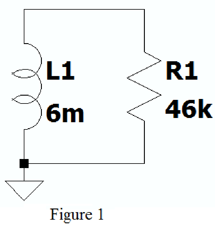
Create the new schematic in LTspice with series connected resistor and inductor of given circuit as shown in Figure 1.
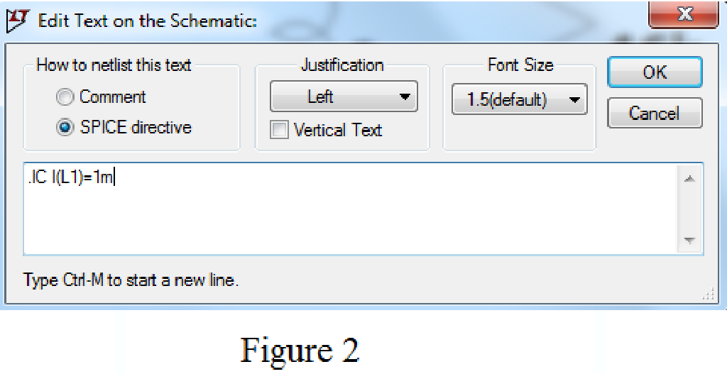
Using SPICE Directive mention the command .ic I(L1)=1m as shown in Figure 2.
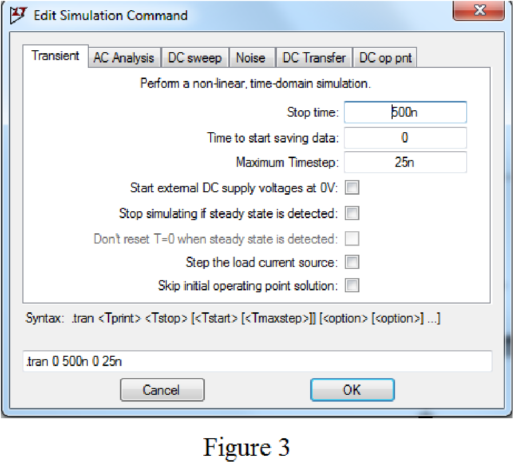
Enter the stop time as 500ns, time to start saving data as 0, and maximum Timestep as 25ns in Edit simulation Cmd as shown in Figure 3.
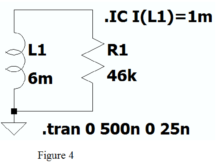
After adding the Spice directives the circuit shows as in Figure 4.
Now run the simulation and place the probe at inductor, the plot of the current through inductor with respect to time is shown as shown in Figure 5.
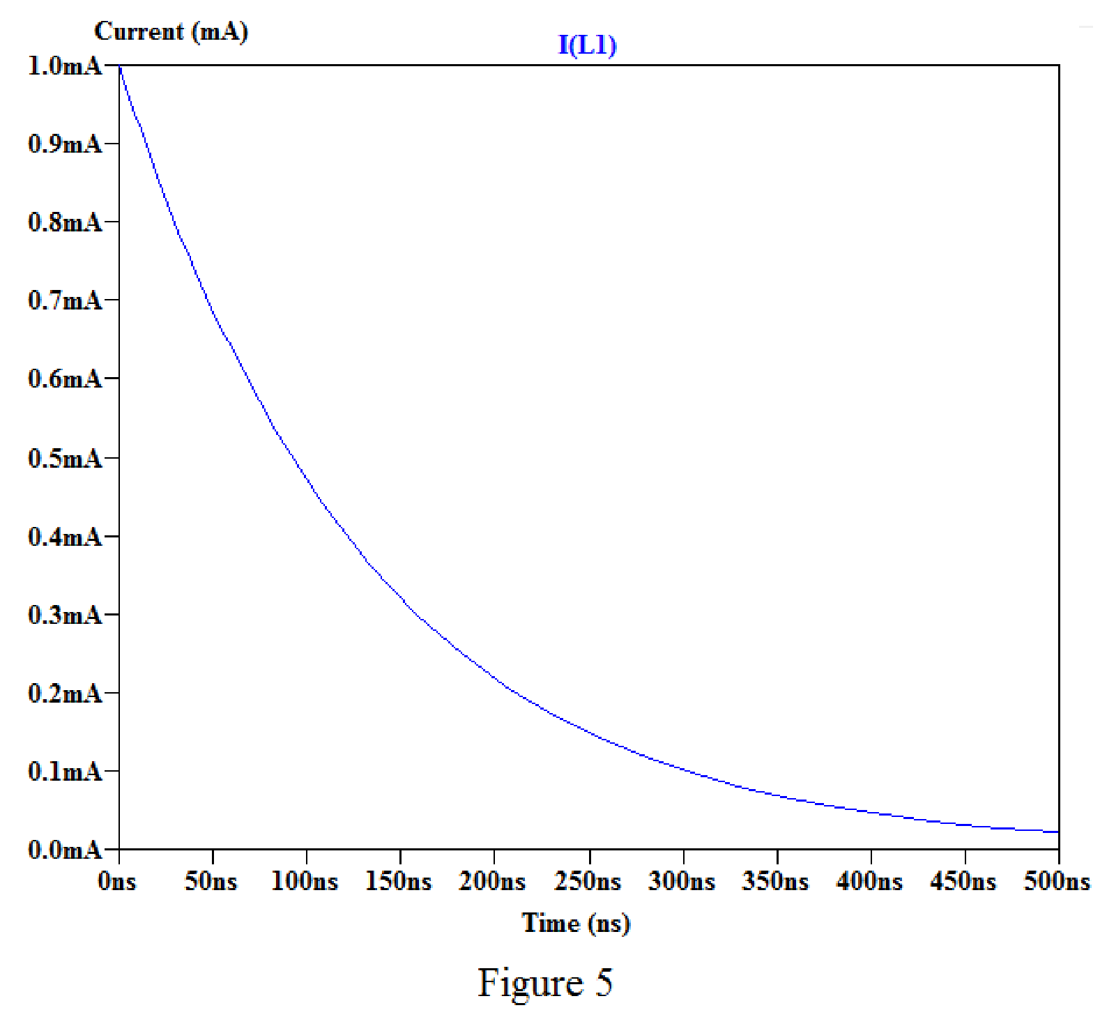
By placing the cursor on the graph, we obtain the current values for different time as shown in below.
For time
For time
For time
For time
Conclusion:
Thus, the value of
(c)
Find the value of initial energy remains in the inductor at time
(c)
Answer to Problem 68E
The value of initial energy remains in the inductor at time
Explanation of Solution
Calculation:
Refer to part (b), the value of current at time
Substitute
Substitute
Simplify the above equation to find
Substitute
Substitute
Simplify the above equation to find
Conclusion:
Thus, the value of initial energy remains in the inductor at time
Want to see more full solutions like this?
Chapter 7 Solutions
Loose Leaf for Engineering Circuit Analysis Format: Loose-leaf


- Figure 1(a) shows the voltage, Vout measured across the capacitor C2 in Figure 1(b). Find the expression of current, I(t) for 0 ms < t< 6 ms. Draw the waveform of this current.arrow_forwardMULTIPLE SELECTION In an intrinsic semiconductor, if the fermi-level exists at the center of the energy gap, then,which of the following conditions holds true ? A Nc = Nv B mn = mp C T = 300K D T = OKarrow_forward8. A 62.5-µf capacitor is connected in series with a 200,000-ohm resistor and to a 250-volt d-c source. (a) Write the expression for the charging current following the closing of the switch. (b) What is the initial charging current? (c) Calculate the time constant and the charging current at t = t. (d) What will be the initial rate of current change?arrow_forward
- 13 i(1) (A) I (s) If the current flowing through a mH inductor has the waveform shown, what is the voltage at t = 2.5s?arrow_forwardQ1 (True/False): A) The current through the capacitor is inversely proportional to the derivative of the voltage across it: Is it true or false? B) In a typical electronic circuit the capacitor blocks DC and couplest he AC to the next stage of the circuit: Is it true or false? C) The more the value of the stray capacitance , the better it is: Is it true or false?arrow_forward1 A 3.5 H inductor has an internal resistance of 10.5 ohms and is connected in series with 30-ohm resistor and to a dc source of 200V through a switch. At t=0, the switch is closed. Calculate the transient current when t = 150 ms.arrow_forward
- The R-L Circuit: An inductor with an inductance of 2.50 H and a resistance of 7.00 n is connected to the terminals ofa battery with an emf of 6.00 V and an internal resistance of 1.00 n. What is the rate ofincrease of current at the instant when the current is 0.500 A? A) 0.8 A/s B) 0.6 A/s C) 0.4 A/s D) zero E) None of the above.arrow_forwardWhat is the function of the holding capacitor in the circuit of Fig. 7?arrow_forwardCompute the equivalent capacitance Ceq as labeled in Fig. 7.55. HE HE 7 F 4 F Ceq 5 F FIGURE 7.55 1 F H6 8 F 5 F HE 2 F 2 F HE 12 Farrow_forward
- 7. After the 5F capacitor is fully charged with a 9V battery, disconnect the capacitor with the battery and connect it to a 12 N resistor (as shown in the circuit diagram). Flip the switch to close at t=0. 1) The voltage of the capacitor at t=60 second 2) The remaining amount of charges that the capacitor stores at t=60 second 12 0 2) How long does it take for the capacitor to be fully dischargedarrow_forwardA 6-mH inductor is used in a fusion power experiment. If the current through the inductor is 5 sin2(Tt) mA, for all t> 0 s, find the power being delivered to the inductor and the energy stored in it at t= 0.5 s. The power delivered to the inductor is W. The energy stored in the inductor is nJ.arrow_forwardGiven the circuit below a. Find the MAGNITUDE of the current through the capacitor (express answer in mA with 2 decimal places)arrow_forward
 Introductory Circuit Analysis (13th Edition)Electrical EngineeringISBN:9780133923605Author:Robert L. BoylestadPublisher:PEARSON
 Delmar's Standard Textbook Of ElectricityElectrical EngineeringISBN:9781337900348Author:Stephen L. HermanPublisher:Cengage Learning
 Programmable Logic ControllersElectrical EngineeringISBN:9780073373843Author:Frank D. PetruzellaPublisher:McGraw-Hill Education
 Fundamentals of Electric CircuitsElectrical EngineeringISBN:9780078028229Author:Charles K Alexander, Matthew SadikuPublisher:McGraw-Hill Education
 Electric Circuits. (11th Edition)Electrical EngineeringISBN:9780134746968Author:James W. Nilsson, Susan RiedelPublisher:PEARSON
 Engineering ElectromagneticsElectrical EngineeringISBN:9780078028151Author:Hayt, William H. (william Hart), Jr, BUCK, John A.Publisher:Mcgraw-hill Education,