
Loose Leaf for Engineering Circuit Analysis Format: Loose-leaf
9th Edition
ISBN: 9781259989452
Author: Hayt
Publisher: Mcgraw Hill Publishers
expand_more
expand_more
format_list_bulleted
Concept explainers
Videos
Textbook Question
Chapter 7, Problem 62E
(a) Draw the exact dual of the simple circuit shown in Fig. 7.76 and label the new (dual) variables if vs = 2 sin t V. (b) Write a nodal equation for the original circuit and a mesh equation for the dual circuit.
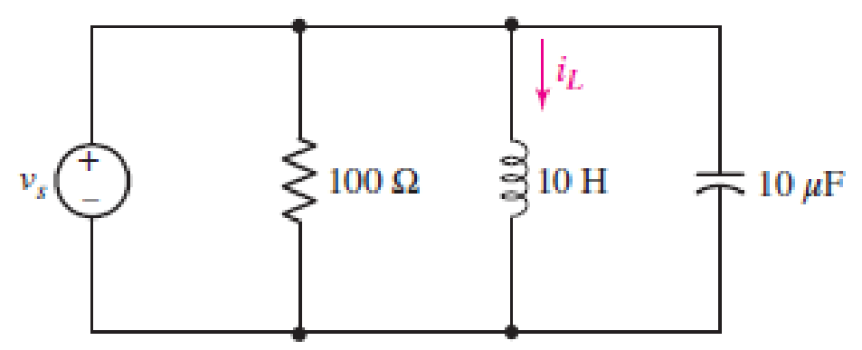
■ FIGURE 7.76
Expert Solution & Answer
Want to see the full answer?
Check out a sample textbook solution
Students have asked these similar questions
Example 7.33. Two coils of inductances 4 and 6 henry are connected in parallel. If their
mutual inductance is 3 henry, calculate the equivalent inductance of the combination if (i) mutual
inductance assists the self-inductance (ii) mutual inductance opposes the self-inductance.
2. 7.22 The switch in the circuit has been in the left positionfor a long time. At t=0 it moves to the right position and stays there. 1. a) Write the expression for the capacitor voltage, v(t), for t≥0
Reduce the circuit depicted in Fig. 7.58 to as few components as possible.
2 V
+
R
W
ww
R
R
M
FIGURE 7.58
с
R
+
Vx
CL
ell
R
мее
L
C
Chapter 7 Solutions
Loose Leaf for Engineering Circuit Analysis Format: Loose-leaf
Ch. 7.1 - Determine the current flowing through a 5 mF...Ch. 7.1 - Prob. 2PCh. 7.1 - Prob. 3PCh. 7.2 - 7.4 The current through a 200 mH inductor is shown...Ch. 7.2 - The current waveform of Fig. 7.14a has equal rise...Ch. 7.2 - Prob. 6PCh. 7.2 - Let L = 25 mH for the inductor of Fig. 7.10. (a)...Ch. 7.3 - Find Ceq for the network of Fig. 7.23. FIGURE...Ch. 7.4 - If vC(t) = 4 cos 105t V in the circuit in Fig....Ch. 7.5 - Derive an expression for vout in terms of vs for...
Ch. 7.6 - Prob. 11PCh. 7 - Making use of the passive sign convention,...Ch. 7 - Prob. 2ECh. 7 - (a) If the voltage waveform depicted in Fig. 7.42...Ch. 7 - A capacitor is constructed from two brass plates,...Ch. 7 - Prob. 5ECh. 7 - Prob. 6ECh. 7 - Design a capacitor whose capacitance can be varied...Ch. 7 - Design a capacitor whose capacitance can be varied...Ch. 7 - Prob. 9ECh. 7 - Assuming the passive sign convention, sketch the...Ch. 7 - Prob. 11ECh. 7 - Prob. 12ECh. 7 - Prob. 13ECh. 7 - Calculate the power dissipated in the 40 resistor...Ch. 7 - Prob. 15ECh. 7 - Design a 30 nH inductor using 28 AWG solid soft...Ch. 7 - Prob. 17ECh. 7 - Prob. 18ECh. 7 - Prob. 19ECh. 7 - Prob. 20ECh. 7 - Calculate vL and iL for each of the circuits...Ch. 7 - The current waveform shown in Fig. 7.14 has a rise...Ch. 7 - Determine the inductor voltage which results from...Ch. 7 - Prob. 24ECh. 7 - The voltage across a 2 H inductor is given by vL =...Ch. 7 - Calculate the energy stored in a 1 nH inductor if...Ch. 7 - Determine the amount of energy stored in a 33 mH...Ch. 7 - Making the assumption that the circuits in Fig....Ch. 7 - Calculate the voltage labeled vx in Fig. 7.52,...Ch. 7 - Prob. 30ECh. 7 - Prob. 31ECh. 7 - Determine an equivalent inductance for the network...Ch. 7 - Using as many 1 nH inductors as you like, design...Ch. 7 - Compute the equivalent capacitance Ceq as labeled...Ch. 7 - Prob. 35ECh. 7 - Prob. 36ECh. 7 - Reduce the circuit depicted in Fig. 7.59 to as few...Ch. 7 - Refer to the network shown in Fig. 7.60 and find...Ch. 7 - Prob. 39ECh. 7 - Prob. 40ECh. 7 - Prob. 41ECh. 7 - Prob. 42ECh. 7 - Prob. 43ECh. 7 - Prob. 44ECh. 7 - Prob. 45ECh. 7 - Prob. 46ECh. 7 - Prob. 47ECh. 7 - Let vs = 100e80t V with no initial energy stored...Ch. 7 - Prob. 49ECh. 7 - Prob. 50ECh. 7 - Interchange the location of R1 and Cf in the...Ch. 7 - For the integrating amplifier circuit of Fig....Ch. 7 - Prob. 53ECh. 7 - For the circuit shown in Fig. 7.73, assume no...Ch. 7 - A new piece of equipment designed to make crystals...Ch. 7 - An altitude sensor on a weather balloon provides a...Ch. 7 - One problem satellites face is exposure to...Ch. 7 - The output of a velocity sensor attached to a...Ch. 7 - A floating sensor in a certain fuel tank is...Ch. 7 - (a) If Is = 3 sin t A, draw the exact dual of the...Ch. 7 - Draw the exact dual of the simple circuit shown in...Ch. 7 - (a) Draw the exact dual of the simple circuit...Ch. 7 - (a) Draw the exact dual of the simple circuit...Ch. 7 - Prob. 64ECh. 7 - Prob. 65ECh. 7 - Prob. 66ECh. 7 - Prob. 67ECh. 7 - Prob. 68ECh. 7 - Prob. 69ECh. 7 - Prob. 70ECh. 7 - For the circuit of Fig. 7.28, (a) sketch vout over...Ch. 7 - (a) Sketch the output function vout of the...Ch. 7 - For the circuit of Fig. 7.72, (a) sketch vout over...
Additional Engineering Textbook Solutions
Find more solutions based on key concepts
Design an ideal inverting op-amp circuit such that the voltage gain is Av=25 . The maximum current in any resis...
Microelectronics: Circuit Analysis and Design
The current source in the circuit shown generates the current pulse
Find (a) v (0); (b) the instant of time gr...
Electric Circuits. (11th Edition)
For the “tank” circuit in Fig. 14.79, find the resonant frequency.
Figure 14.79
For Probs. 14.39, 14.71, and 1...
Fundamentals of Electric Circuits
Explain the main function of each of the following major components of a PLC: a. Processor module (CPU) b. I/O ...
Programmable Logic Controllers
A constant voltage of 10V is applied to a 50H inductance, as shown in Figure P3.51 Figure P3 51 The current in ...
Electrical Engineering: Principles & Applications (7th Edition)
What is the color code for a 365- five-band precision resistor with a tolerance of 5 percent?
ELECTRICITY FOR TRADES (LOOSELEAF)
Knowledge Booster


Learn more about
Need a deep-dive on the concept behind this application? Look no further. Learn more about this topic, electrical-engineering and related others by exploring similar questions and additional content below.Similar questions
- 7.49.2 For the RC circuit shown in the image below, the current waveform is applied. If v (0) = 0, R1 = 4 S2 and R2 = 9 $2, determine the voltage across the capacitor, v when t = 1.1 s. Please pay attention: the numbers may change since they are randomized. Your answer must include 3 places after the decimal point, and the proper SI unit. is (A) A 1 t (s) (a) R2 + is R, 0.5 F (b) Your Answer: Answer unitsarrow_forwardElectromagnet, picture 2 is an example of doing Practice Exercise 7.7, thank you in advance.arrow_forwardSolution: Redrawing the network after combining series e yields Fig. 7.23, and Is 16 24 k) 24 kN R6 12 kN R1,2,3 R4 Is E=72 V R7 R8.9 V7 9 kS R5 12 kN 9 kΩ Is 16 FIG. 7.23 Network of Fig. 7.22 redrawn.arrow_forward
- A 100µF capacitor is connected in series with a 150volt voltmeter that has a resistance of 1,000 ohms per volt. Calculate the reading of the voltmeter at the instant when t equals the time constant following the closing if the switch that impresses 120volts on the circuit.arrow_forward3. Express the following signals in terms of singularity functions: v(1) A 1 -1 -1 a. Singularity Function vý(t) / 2 0 2 4 b. Singularity Function Correct and complete solution Please Explain the solution Thank youarrow_forwardQuestion 32 Determine an equivalent inductance for the network shown in Fig. 7.54 if each inductor has value L. O rele Ay ell FIGURE 7.54 rellarrow_forward
- Question 25: For the circuit shown in Figure 7.76, find: (a) the current and the potential difference for each resistor; (b) the potential difference VA - VB (the directions given to the currents in the figure are arbitrary). (c) Check that the net power supplied by the batteries is fully transformed into heat in the resistors. Answer: (a) I2= 3.00 A ; I2= 1.00 A, in the opposite direction of the figure ; I3= 4,00 A in the opposite direction of the figure; ∆VR1= 6.00 V ; ∆VR2= 5.00 V ; ∆VR3= 20.0 V ; (b) -20.0 V (c) 103W *Please show steps, formulas and explanation for my own understanding. Thank youarrow_forward2. For the fixed-bias configuration of Fig. 7.76, determine: a. Ipo and VGS using a purely mathematical approach. b. Repeat part (a) using a graphical approach and compare results. c. Find Vps, VD, VG, and Vs using the results of part (a). -3 V * 1.2 ΜΩ VGSQ 16 V 1 2.2 ΚΩ PROBLEMS Fixed-Bias Configuration 100 pss = 10 mA Vp = -4.5V 3. Given the measured value of V₁ in Fig. 7.77, determine: a. Ip. b. Vps. c. VGG VD=6V 12 V 2.2 kΩ ID VGS 10 = 1 (1 - Vec)² ID Vp + VDS Inss=8 mA Vp=-4 V FIG. 7.77 Problem 3. 1 ΜΩ -VGG 50arrow_forward. Calculate v, and i̟ for each of the circuits depicted in Fig. 7.48, if i, = 1 mA and v, = 2.1 V. iL 14 kN is 12 nH 4.7 kN llarrow_forward
- Fig. 7.4.3 3. Period of v(t) 5cos (10t/4 + 60) equals to, value of v(t) at period 10ms is equal to: A) 0.6283 s, 1.144 v B) 6.283 s, 2.38 v C) 12.455 s, 1.04 v D) 5.243 s, 2.28 varrow_forward*The switch shown in (Figure 1) has been open for a long time before closing at t = 0.* Pt A. Choose the correct expression for the capacitor voltage, v(t), for t≥0arrow_forwardFor the circuit shown Figure 3, Calculate the expression of the i(t) assume the initial value of inductor initial value voltage capacitors is zero. V =e-Stv. 0.IF 20 0.5F Figure 3arrow_forward
arrow_back_ios
SEE MORE QUESTIONS
arrow_forward_ios
Recommended textbooks for you
 Introductory Circuit Analysis (13th Edition)Electrical EngineeringISBN:9780133923605Author:Robert L. BoylestadPublisher:PEARSON
 Delmar's Standard Textbook Of ElectricityElectrical EngineeringISBN:9781337900348Author:Stephen L. HermanPublisher:Cengage Learning
 Programmable Logic ControllersElectrical EngineeringISBN:9780073373843Author:Frank D. PetruzellaPublisher:McGraw-Hill Education
 Fundamentals of Electric CircuitsElectrical EngineeringISBN:9780078028229Author:Charles K Alexander, Matthew SadikuPublisher:McGraw-Hill Education
 Electric Circuits. (11th Edition)Electrical EngineeringISBN:9780134746968Author:James W. Nilsson, Susan RiedelPublisher:PEARSON
 Engineering ElectromagneticsElectrical EngineeringISBN:9780078028151Author:Hayt, William H. (william Hart), Jr, BUCK, John A.Publisher:Mcgraw-hill Education,
Introductory Circuit Analysis (13th Edition)
Electrical Engineering
ISBN:9780133923605
Author:Robert L. Boylestad
Publisher:PEARSON
Delmar's Standard Textbook Of Electricity
Electrical Engineering
ISBN:9781337900348
Author:Stephen L. Herman
Publisher:Cengage Learning
Programmable Logic Controllers
Electrical Engineering
ISBN:9780073373843
Author:Frank D. Petruzella
Publisher:McGraw-Hill Education
Fundamentals of Electric Circuits
Electrical Engineering
ISBN:9780078028229
Author:Charles K Alexander, Matthew Sadiku
Publisher:McGraw-Hill Education
Electric Circuits. (11th Edition)
Electrical Engineering
ISBN:9780134746968
Author:James W. Nilsson, Susan Riedel
Publisher:PEARSON
Engineering Electromagnetics
Electrical Engineering
ISBN:9780078028151
Author:Hayt, William H. (william Hart), Jr, BUCK, John A.
Publisher:Mcgraw-hill Education,
ENA 9.2(1)(En)(Alex) Sinusoids & Phasors - Explanation with Example 9.1 ,9.2 & PP 9.2; Author: Electrical Engineering Academy;https://www.youtube.com/watch?v=vX_LLNl-ZpU;License: Standard YouTube License, CC-BY
Electrical Engineering: Ch 10 Alternating Voltages & Phasors (8 of 82) What is a Phasor?; Author: Michel van Biezen;https://www.youtube.com/watch?v=2I1tF3ixNg0;License: Standard Youtube License