
Loose Leaf for Engineering Circuit Analysis Format: Loose-leaf
9th Edition
ISBN: 9781259989452
Author: Hayt
Publisher: Mcgraw Hill Publishers
expand_more
expand_more
format_list_bulleted
Concept explainers
Videos
Textbook Question
Chapter 7.3, Problem 8P
Find Ceq for the network of Fig. 7.23.
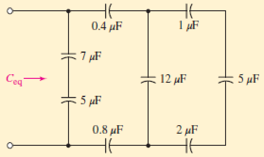
■ FIGURE 7.23
Expert Solution & Answer
Want to see the full answer?
Check out a sample textbook solution
Students have asked these similar questions
Rp
->
sa
Figure 7.52 Bia
resistance, RG
Electromagnet, picture 2 is an example of doing Practice Exercise 7.7, thank you in advance.
Please answer 7.16
Chapter 7 Solutions
Loose Leaf for Engineering Circuit Analysis Format: Loose-leaf
Ch. 7.1 - Determine the current flowing through a 5 mF...Ch. 7.1 - Prob. 2PCh. 7.1 - Prob. 3PCh. 7.2 - 7.4 The current through a 200 mH inductor is shown...Ch. 7.2 - The current waveform of Fig. 7.14a has equal rise...Ch. 7.2 - Prob. 6PCh. 7.2 - Let L = 25 mH for the inductor of Fig. 7.10. (a)...Ch. 7.3 - Find Ceq for the network of Fig. 7.23. FIGURE...Ch. 7.4 - If vC(t) = 4 cos 105t V in the circuit in Fig....Ch. 7.5 - Derive an expression for vout in terms of vs for...
Ch. 7.6 - Prob. 11PCh. 7 - Making use of the passive sign convention,...Ch. 7 - Prob. 2ECh. 7 - (a) If the voltage waveform depicted in Fig. 7.42...Ch. 7 - A capacitor is constructed from two brass plates,...Ch. 7 - Prob. 5ECh. 7 - Prob. 6ECh. 7 - Design a capacitor whose capacitance can be varied...Ch. 7 - Design a capacitor whose capacitance can be varied...Ch. 7 - Prob. 9ECh. 7 - Assuming the passive sign convention, sketch the...Ch. 7 - Prob. 11ECh. 7 - Prob. 12ECh. 7 - Prob. 13ECh. 7 - Calculate the power dissipated in the 40 resistor...Ch. 7 - Prob. 15ECh. 7 - Design a 30 nH inductor using 28 AWG solid soft...Ch. 7 - Prob. 17ECh. 7 - Prob. 18ECh. 7 - Prob. 19ECh. 7 - Prob. 20ECh. 7 - Calculate vL and iL for each of the circuits...Ch. 7 - The current waveform shown in Fig. 7.14 has a rise...Ch. 7 - Determine the inductor voltage which results from...Ch. 7 - Prob. 24ECh. 7 - The voltage across a 2 H inductor is given by vL =...Ch. 7 - Calculate the energy stored in a 1 nH inductor if...Ch. 7 - Determine the amount of energy stored in a 33 mH...Ch. 7 - Making the assumption that the circuits in Fig....Ch. 7 - Calculate the voltage labeled vx in Fig. 7.52,...Ch. 7 - Prob. 30ECh. 7 - Prob. 31ECh. 7 - Determine an equivalent inductance for the network...Ch. 7 - Using as many 1 nH inductors as you like, design...Ch. 7 - Compute the equivalent capacitance Ceq as labeled...Ch. 7 - Prob. 35ECh. 7 - Prob. 36ECh. 7 - Reduce the circuit depicted in Fig. 7.59 to as few...Ch. 7 - Refer to the network shown in Fig. 7.60 and find...Ch. 7 - Prob. 39ECh. 7 - Prob. 40ECh. 7 - Prob. 41ECh. 7 - Prob. 42ECh. 7 - Prob. 43ECh. 7 - Prob. 44ECh. 7 - Prob. 45ECh. 7 - Prob. 46ECh. 7 - Prob. 47ECh. 7 - Let vs = 100e80t V with no initial energy stored...Ch. 7 - Prob. 49ECh. 7 - Prob. 50ECh. 7 - Interchange the location of R1 and Cf in the...Ch. 7 - For the integrating amplifier circuit of Fig....Ch. 7 - Prob. 53ECh. 7 - For the circuit shown in Fig. 7.73, assume no...Ch. 7 - A new piece of equipment designed to make crystals...Ch. 7 - An altitude sensor on a weather balloon provides a...Ch. 7 - One problem satellites face is exposure to...Ch. 7 - The output of a velocity sensor attached to a...Ch. 7 - A floating sensor in a certain fuel tank is...Ch. 7 - (a) If Is = 3 sin t A, draw the exact dual of the...Ch. 7 - Draw the exact dual of the simple circuit shown in...Ch. 7 - (a) Draw the exact dual of the simple circuit...Ch. 7 - (a) Draw the exact dual of the simple circuit...Ch. 7 - Prob. 64ECh. 7 - Prob. 65ECh. 7 - Prob. 66ECh. 7 - Prob. 67ECh. 7 - Prob. 68ECh. 7 - Prob. 69ECh. 7 - Prob. 70ECh. 7 - For the circuit of Fig. 7.28, (a) sketch vout over...Ch. 7 - (a) Sketch the output function vout of the...Ch. 7 - For the circuit of Fig. 7.72, (a) sketch vout over...
Knowledge Booster


Learn more about
Need a deep-dive on the concept behind this application? Look no further. Learn more about this topic, electrical-engineering and related others by exploring similar questions and additional content below.Similar questions
- Determine vo for the circuit shown in Figure 7.98(a) and (b). 12 V Si 22 ka Si 1.8 k2 10 k2 -12 V (a) (b) Figure 7.8arrow_forwardCalculate vL and ir for each of the circuits depicted in Fig. 7.48, if i, = 1 mA and v, = 2 V. 4.7 kΩ 14 kΩ 12 nH 12 nH 4.7 kN elearrow_forwardUsing Thevenin's Theorem, rewrite the physical network from Figure 7 as an equivalent Thevenin Network, i.e. express Veq as a function of V₁ and V₁ and Req as a value. If the voltage sources Vo and V₁ are the outputs of digital pins on an Arduino (i.e. 0 volts or 5 volts), what are the four possible values of Veq? + Vol + 2R Physical circuit 2R VO m 3.3ΚΩ m t Figure 7: Resistor Network for Thevinin's Theorem Using Thevenin's Theorem rewrite Vout from Figure 8 as a function of vo through v3. We will consider these voltages to be the inputs of this circuit. Since they are inputs, they can also be thought of as implicitly declared volt- age sources. You may expand vo through v3 as voltage sources (referenced to ground) to make the circuit more clear. For analysis, you will find it most useful to break the circuit and cascade Thevenin's Theorem from the left most point to the right most point. Note the pattern that appears with each additional R-2R m R Vout section in your prelab. If the…arrow_forward
- 15. For the network of Fig. 7.78: a. Determine the current I. b. Find V V = +9 V R2 R3 2 = -19 V %3D FIG. 7.78 Problem 15.arrow_forwardIn circuit of this exercise the negative terminals of the sources are connected to ground. Is this a requirement for mesh analysis? What would happen to the mesh currents if the positions of E1 and R1 in Figure 7.1 were swapped?arrow_forward2. Given the milliammeter readings appearing in Fig. 7.9, determine the resistances R₁ and R₂. Assume Rinternal = 0 for all meters. FIG. 7.9 R₁ = O 8.8 mA R₁ R₂ = www R₂ O 4.8 mA www 4 mA R Network with input resistance R = 2 kΩarrow_forward
- Solution: Redrawing the network after combining series e yields Fig. 7.23, and Is 16 24 k) 24 kN R6 12 kN R1,2,3 R4 Is E=72 V R7 R8.9 V7 9 kS R5 12 kN 9 kΩ Is 16 FIG. 7.23 Network of Fig. 7.22 redrawn.arrow_forwardQuestion 7.11 Find VS for the network of Fig. 7.89.arrow_forward× 7:53 www.bartleby.com Homework Help is Here - Start Your Trial Now! Q SEARCH Textbook Question 个 R₁ = 7,2 kn Fig. 7.69 Chapter 7, Problem 6P The total resistance R+ for the network of Fig. 7.69. is 7.2 k Find the resistance R. R₁ vport Solution ASK R₁ il 5GE ncwa R₁ R₁ G ●●● → 2arrow_forward
- 7.1 Consider PV module A whose characteristics are shown in Table 7.3. Com- pute: The cell temperature if the irradiance is 1000 W/m² and the ambient temperature is 31°C The short-circuit current, open-circuit voltage, and maximum power if the irradiance is 1000 W/m² and the cell temperature is as computed in the previous part of this problem The short-circuit current if the irradiance is 500 W/m2 The power produced using Osterwald's method if the irradiance is 650 W/m² and the ambient temperature is 20°Carrow_forward. Calculate v, and i̟ for each of the circuits depicted in Fig. 7.48, if i, = 1 mA and v, = 2.1 V. iL 14 kN is 12 nH 4.7 kN llarrow_forwardPROBLE M 7.15 Determine VOUT versus vIN for the circuit shown in Figure 7.8 Assume that the MOSFET operates in saturation and is characterized by the paramete K and VT. What is the value of VOUT when VỊN = 0? PROBLEM 7.16 Determine vo versus vị for the circuit shown in Figure 7.8 Assume that the MOSFET operates in saturation and is characterized by the paramete K and VT. What is the value of vo when vj = = 0?arrow_forward
arrow_back_ios
SEE MORE QUESTIONS
arrow_forward_ios
Recommended textbooks for you
 Introductory Circuit Analysis (13th Edition)Electrical EngineeringISBN:9780133923605Author:Robert L. BoylestadPublisher:PEARSON
 Delmar's Standard Textbook Of ElectricityElectrical EngineeringISBN:9781337900348Author:Stephen L. HermanPublisher:Cengage Learning
 Programmable Logic ControllersElectrical EngineeringISBN:9780073373843Author:Frank D. PetruzellaPublisher:McGraw-Hill Education
 Fundamentals of Electric CircuitsElectrical EngineeringISBN:9780078028229Author:Charles K Alexander, Matthew SadikuPublisher:McGraw-Hill Education
 Electric Circuits. (11th Edition)Electrical EngineeringISBN:9780134746968Author:James W. Nilsson, Susan RiedelPublisher:PEARSON
 Engineering ElectromagneticsElectrical EngineeringISBN:9780078028151Author:Hayt, William H. (william Hart), Jr, BUCK, John A.Publisher:Mcgraw-hill Education,
Introductory Circuit Analysis (13th Edition)
Electrical Engineering
ISBN:9780133923605
Author:Robert L. Boylestad
Publisher:PEARSON
Delmar's Standard Textbook Of Electricity
Electrical Engineering
ISBN:9781337900348
Author:Stephen L. Herman
Publisher:Cengage Learning
Programmable Logic Controllers
Electrical Engineering
ISBN:9780073373843
Author:Frank D. Petruzella
Publisher:McGraw-Hill Education
Fundamentals of Electric Circuits
Electrical Engineering
ISBN:9780078028229
Author:Charles K Alexander, Matthew Sadiku
Publisher:McGraw-Hill Education
Electric Circuits. (11th Edition)
Electrical Engineering
ISBN:9780134746968
Author:James W. Nilsson, Susan Riedel
Publisher:PEARSON
Engineering Electromagnetics
Electrical Engineering
ISBN:9780078028151
Author:Hayt, William H. (william Hart), Jr, BUCK, John A.
Publisher:Mcgraw-hill Education,
Current Divider Rule; Author: Neso Academy;https://www.youtube.com/watch?v=hRU1mKWUehY;License: Standard YouTube License, CC-BY