
Loose Leaf for Engineering Circuit Analysis Format: Loose-leaf
9th Edition
ISBN: 9781259989452
Author: Hayt
Publisher: Mcgraw Hill Publishers
expand_more
expand_more
format_list_bulleted
Concept explainers
Videos
Textbook Question
Chapter 7.4, Problem 9P
If vC(t) = 4 cos 105t V in the circuit in Fig. 7.26, find vs(t).
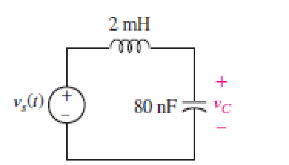
FIGURE 7.26
Expert Solution & Answer
Want to see the full answer?
Check out a sample textbook solution
Students have asked these similar questions
Problem 1 (time constant in RC Circuits, Alexander 7.2)
120 Ω
12Ω
ww
50 V (+
80 Ω
200 mF
Figure P1
Find the time constant for the RC circuit in Figure P1.
ww
In the circuit of Fig. 7.101, find the value of Red for which the steady-state energy
stored in the inductor will be 1 J.
60 V
40 22
www
ww
R
www
80 Ω
2 H
7.53 Determine the inductor current i(t) for both t 0 for each of the circuits in Fig. 7.119.
25 V
6 A
352
ww
t=0
(a)
t=0
4Ω
252
252
4 H
3 H
of switch open for t=0-
* Switch closed fer
t = 0²
Chapter 7 Solutions
Loose Leaf for Engineering Circuit Analysis Format: Loose-leaf
Ch. 7.1 - Determine the current flowing through a 5 mF...Ch. 7.1 - Prob. 2PCh. 7.1 - Prob. 3PCh. 7.2 - 7.4 The current through a 200 mH inductor is shown...Ch. 7.2 - The current waveform of Fig. 7.14a has equal rise...Ch. 7.2 - Prob. 6PCh. 7.2 - Let L = 25 mH for the inductor of Fig. 7.10. (a)...Ch. 7.3 - Find Ceq for the network of Fig. 7.23. FIGURE...Ch. 7.4 - If vC(t) = 4 cos 105t V in the circuit in Fig....Ch. 7.5 - Derive an expression for vout in terms of vs for...
Ch. 7.6 - Prob. 11PCh. 7 - Making use of the passive sign convention,...Ch. 7 - Prob. 2ECh. 7 - (a) If the voltage waveform depicted in Fig. 7.42...Ch. 7 - A capacitor is constructed from two brass plates,...Ch. 7 - Prob. 5ECh. 7 - Prob. 6ECh. 7 - Design a capacitor whose capacitance can be varied...Ch. 7 - Design a capacitor whose capacitance can be varied...Ch. 7 - Prob. 9ECh. 7 - Assuming the passive sign convention, sketch the...Ch. 7 - Prob. 11ECh. 7 - Prob. 12ECh. 7 - Prob. 13ECh. 7 - Calculate the power dissipated in the 40 resistor...Ch. 7 - Prob. 15ECh. 7 - Design a 30 nH inductor using 28 AWG solid soft...Ch. 7 - Prob. 17ECh. 7 - Prob. 18ECh. 7 - Prob. 19ECh. 7 - Prob. 20ECh. 7 - Calculate vL and iL for each of the circuits...Ch. 7 - The current waveform shown in Fig. 7.14 has a rise...Ch. 7 - Determine the inductor voltage which results from...Ch. 7 - Prob. 24ECh. 7 - The voltage across a 2 H inductor is given by vL =...Ch. 7 - Calculate the energy stored in a 1 nH inductor if...Ch. 7 - Determine the amount of energy stored in a 33 mH...Ch. 7 - Making the assumption that the circuits in Fig....Ch. 7 - Calculate the voltage labeled vx in Fig. 7.52,...Ch. 7 - Prob. 30ECh. 7 - Prob. 31ECh. 7 - Determine an equivalent inductance for the network...Ch. 7 - Using as many 1 nH inductors as you like, design...Ch. 7 - Compute the equivalent capacitance Ceq as labeled...Ch. 7 - Prob. 35ECh. 7 - Prob. 36ECh. 7 - Reduce the circuit depicted in Fig. 7.59 to as few...Ch. 7 - Refer to the network shown in Fig. 7.60 and find...Ch. 7 - Prob. 39ECh. 7 - Prob. 40ECh. 7 - Prob. 41ECh. 7 - Prob. 42ECh. 7 - Prob. 43ECh. 7 - Prob. 44ECh. 7 - Prob. 45ECh. 7 - Prob. 46ECh. 7 - Prob. 47ECh. 7 - Let vs = 100e80t V with no initial energy stored...Ch. 7 - Prob. 49ECh. 7 - Prob. 50ECh. 7 - Interchange the location of R1 and Cf in the...Ch. 7 - For the integrating amplifier circuit of Fig....Ch. 7 - Prob. 53ECh. 7 - For the circuit shown in Fig. 7.73, assume no...Ch. 7 - A new piece of equipment designed to make crystals...Ch. 7 - An altitude sensor on a weather balloon provides a...Ch. 7 - One problem satellites face is exposure to...Ch. 7 - The output of a velocity sensor attached to a...Ch. 7 - A floating sensor in a certain fuel tank is...Ch. 7 - (a) If Is = 3 sin t A, draw the exact dual of the...Ch. 7 - Draw the exact dual of the simple circuit shown in...Ch. 7 - (a) Draw the exact dual of the simple circuit...Ch. 7 - (a) Draw the exact dual of the simple circuit...Ch. 7 - Prob. 64ECh. 7 - Prob. 65ECh. 7 - Prob. 66ECh. 7 - Prob. 67ECh. 7 - Prob. 68ECh. 7 - Prob. 69ECh. 7 - Prob. 70ECh. 7 - For the circuit of Fig. 7.28, (a) sketch vout over...Ch. 7 - (a) Sketch the output function vout of the...Ch. 7 - For the circuit of Fig. 7.72, (a) sketch vout over...
Knowledge Booster


Learn more about
Need a deep-dive on the concept behind this application? Look no further. Learn more about this topic, electrical-engineering and related others by exploring similar questions and additional content below.Similar questions
- 7.79 Find V, in the circuit of Fig. P7.79. j4N 5Ω 5Ω 10 V -j2 0 Vo Figure P7.79: Circuit for Problem 7.79. + )arrow_forwardDetermine the inductor current i(t) for t > 0 for the circuits in Fig. 7.119. 6 A 4Ω 3 H Fig. 7.119 ell wwarrow_forwardCompute the equivalent capacitance Ceq as labeled in Fig. 7.55. HE HE 7 F 4 F Ceq 5 F FIGURE 7.55 1 F H6 8 F 5 F HE 2 F 2 F HE 12 Farrow_forward
- Consider the circuit in Fig. 7.103. Given that v(0) = 10 V, find v, and vz for t > 0. %3D 3Ω ww 10 H3 20arrow_forward7.39 Calculate the capacitor voltage for t 0 for each of the circuits in Fig. 7.106. 20 V 12 V (4+1 402 www 2F +v- www 392 1+ V2F (a) 192 (b) засто 1=040 2Aarrow_forward7.17 Consider the circuit of Fig. 7.97. Find v„(1) if i(0) = 6 A and v(1) = 0. ww- 32arrow_forward
- Practice Problem 7.1 892 www + 1292 6Ω VC Figure 7.7 For Practice Prob. 7.1. www Refer to the circuit in Fig. 7.7. Let vc(0) = 60 V. Determine Uc, Ux² and i, for t≥ 0. Answer: 60e-0.25 V, 20e-0.25 V, -5e-0.25t A.arrow_forwardExample 7.8: Apply nodal analysis to the network in Fig. 7.6(a). so www 40 2A R₁100 EMV W 40 -0 2A 100arrow_forward7.3. For the following circuit, find the mathematical expressions for ic(t) and Vċ(t) in the interval Os ≤ t ≤ 2s and graph them by hand. 10u(t - 0,5) mA ww 5 ΚΩ ww • 10 ΚΩ VC 10 ΚΩ M + ic 15 ΚΩ M 0.1 mF +100u(t-1,5) Varrow_forward
- b) What is the current at t = 0.008 s? (In [A]) c) What is the voltage at t = 0.008 s? (in [V]) Hint: What relationships exist between voltage and current when the current in an inductor is interrupted?arrow_forwardDerive an expression for vout in terms of us for the amplifier circuit shown in Fig. 7.71. Rf L₁ m # Vs FIGURE 7.71 9 + Voutarrow_forward7:44 ( Teams PBL-1 Your Friend Saad was selected to attend the Electronics workshop on “Electronic Circuits" organized by the university. In the workshop, he was exposed to many topics such as voltage divider circuits, dependent voltage source, dependent current source, independent voltage source, independent current source, application of Thevenin and Norton theorem, maximum power transfer. There were some customers’ requirements same were discussed in the workshop. Apply the concepts of the above-mentioned topics, each participant must fulfill the customer requirements. I) The input available DC voltage is 220 V and customer wants to supply the output of 30V and 50V. The available ready stock is source voltage as mentioned above and resistors values can be chosen from 1-300 KQ. Apply the concept of voltage divider with values of resistance is in k2, one value of the resistor is the last digit of your NUTECH ID and other may vary (depend on your calculations). II) Now you have two…arrow_forward
arrow_back_ios
SEE MORE QUESTIONS
arrow_forward_ios
Recommended textbooks for you
 Introductory Circuit Analysis (13th Edition)Electrical EngineeringISBN:9780133923605Author:Robert L. BoylestadPublisher:PEARSON
 Delmar's Standard Textbook Of ElectricityElectrical EngineeringISBN:9781337900348Author:Stephen L. HermanPublisher:Cengage Learning
 Programmable Logic ControllersElectrical EngineeringISBN:9780073373843Author:Frank D. PetruzellaPublisher:McGraw-Hill Education
 Fundamentals of Electric CircuitsElectrical EngineeringISBN:9780078028229Author:Charles K Alexander, Matthew SadikuPublisher:McGraw-Hill Education
 Electric Circuits. (11th Edition)Electrical EngineeringISBN:9780134746968Author:James W. Nilsson, Susan RiedelPublisher:PEARSON
 Engineering ElectromagneticsElectrical EngineeringISBN:9780078028151Author:Hayt, William H. (william Hart), Jr, BUCK, John A.Publisher:Mcgraw-hill Education,
Introductory Circuit Analysis (13th Edition)
Electrical Engineering
ISBN:9780133923605
Author:Robert L. Boylestad
Publisher:PEARSON
Delmar's Standard Textbook Of Electricity
Electrical Engineering
ISBN:9781337900348
Author:Stephen L. Herman
Publisher:Cengage Learning
Programmable Logic Controllers
Electrical Engineering
ISBN:9780073373843
Author:Frank D. Petruzella
Publisher:McGraw-Hill Education
Fundamentals of Electric Circuits
Electrical Engineering
ISBN:9780078028229
Author:Charles K Alexander, Matthew Sadiku
Publisher:McGraw-Hill Education
Electric Circuits. (11th Edition)
Electrical Engineering
ISBN:9780134746968
Author:James W. Nilsson, Susan Riedel
Publisher:PEARSON
Engineering Electromagnetics
Electrical Engineering
ISBN:9780078028151
Author:Hayt, William H. (william Hart), Jr, BUCK, John A.
Publisher:Mcgraw-hill Education,
ENA 9.2(1)(En)(Alex) Sinusoids & Phasors - Explanation with Example 9.1 ,9.2 & PP 9.2; Author: Electrical Engineering Academy;https://www.youtube.com/watch?v=vX_LLNl-ZpU;License: Standard YouTube License, CC-BY
Electrical Engineering: Ch 10 Alternating Voltages & Phasors (8 of 82) What is a Phasor?; Author: Michel van Biezen;https://www.youtube.com/watch?v=2I1tF3ixNg0;License: Standard Youtube License