
Loose Leaf for Engineering Circuit Analysis Format: Loose-leaf
9th Edition
ISBN: 9781259989452
Author: Hayt
Publisher: Mcgraw Hill Publishers
expand_more
expand_more
format_list_bulleted
Videos
Textbook Question
Chapter 3, Problem 20E
In the circuit of Fig. 3.55, calculate the voltage across the dependent source (“+” reference on top) if V2 is 15 V, and IB is 20 μA.
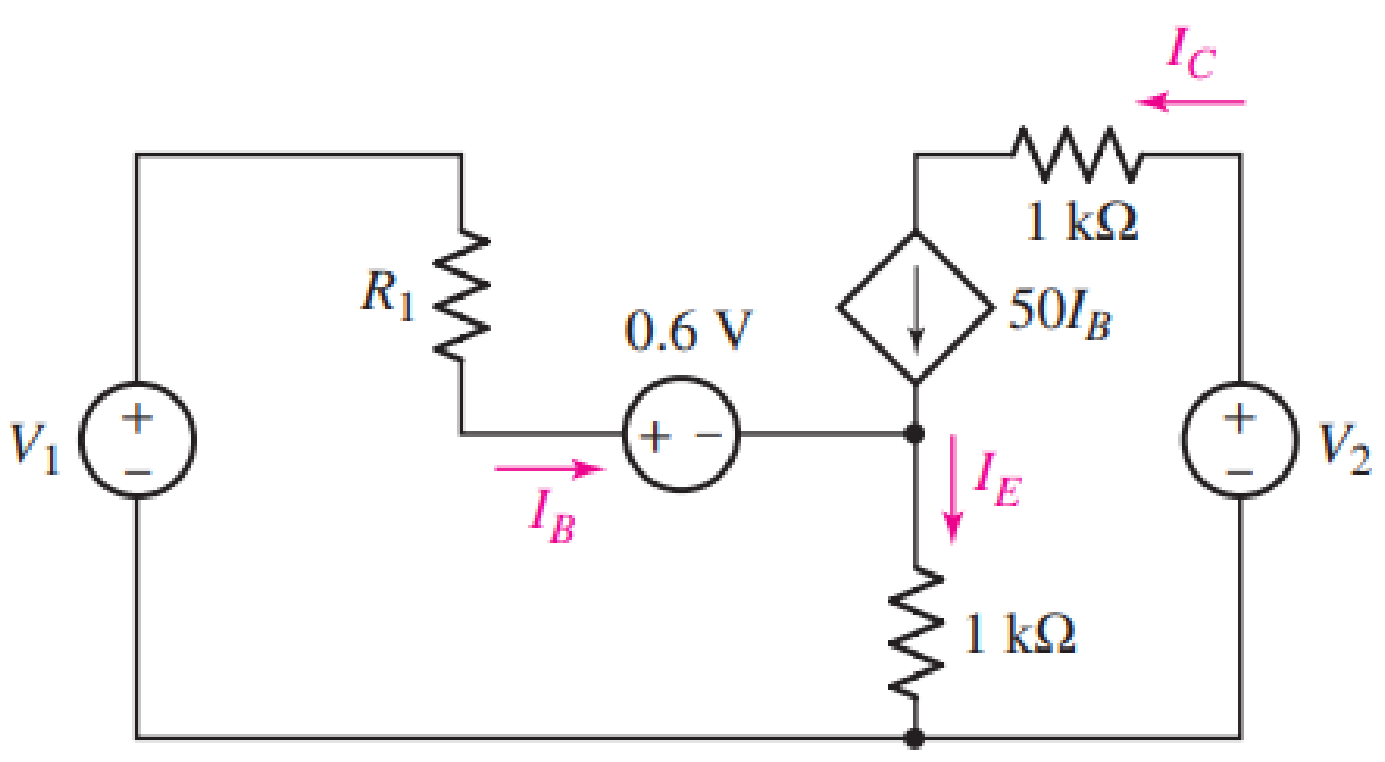
FIGURE 3.55
Expert Solution & Answer
Want to see the full answer?
Check out a sample textbook solution
Students have asked these similar questions
A 230-V, 1 000-c/s voltage is applied to a resistor in series
with C
capacıtance 0 06 µF, the reading is 100 V. Find the current
when the voltmeter is disconnected.
86
0 05 µF. When C is shunted by a voltmeter of
[0 0527 A.]
3.1 Find the equivalent resistance Rab for each of the circuits in the following figure.
a
b
5052 9052
{30012
802
$10052 $7052
Q3.Design an Ayrton shunt by indirect method to provide an ammeter with current ranges,
2A, 6A, 12A, If PMMC meter have internal resistance of 30 2 and full scale current of
1mA.
2A
Ra
+o
I
12A
6 A
w
Rb
Re
E
Im
Rm
Chapter 3 Solutions
Loose Leaf for Engineering Circuit Analysis Format: Loose-leaf
Ch. 3.2 - 3.1 (a) Count the number of branches and nodes in...Ch. 3.3 - Determine ix and vx in the circuit of Fig. 3.7....Ch. 3.3 - For the circuit of Fig. 3.9, if vR1=1V, determine...Ch. 3.3 - Determine vx in the circuit of Fig. 3.11.Ch. 3.4 - In the circuit of Fig. 3.12b, vs1 = 120 V, vs2 =...Ch. 3.4 - 3.6 In the circuit of Fig. 3.14, find the power...Ch. 3.5 - Determine v in the circuit of Fig. 3.16.Ch. 3.5 - For the single-node-pair circuit of Fig. 3.18,...Ch. 3.6 - Determine the current i in the circuit of Fig....Ch. 3.6 - Determine the voltage v in the circuit of Fig....
Ch. 3.6 - Determine whether the circuit of Fig. 3.25...Ch. 3.7 - 3.12 Determine a single-value equivalent...Ch. 3.7 - 3.13 Determine i in the circuit of Fig. 3.29....Ch. 3.7 - Determine v in the circuit of Fig. 3.31 by first...Ch. 3.7 - 3.15 For the circuit of Fig. 3.33, calculate the...Ch. 3.8 - 3.16 Use voltage division to determine vx in the...Ch. 3.8 - In the circuit of Fig. 3.40, use resistance...Ch. 3 - Referring to the circuit depicted in Fig. 3.45,...Ch. 3 - Referring to the circuit depicted in Fig. 3.46,...Ch. 3 - For the circuit of Fig. 3.47: (a) Count the number...Ch. 3 - For the circuit of Fig. 3.47: (a) Count the number...Ch. 3 - Refer to the circuit of Fig. 3.48, and answer the...Ch. 3 - A local restaurant has a neon sign constructed...Ch. 3 - Referring to the single-node diagram of Fig. 3.50,...Ch. 3 - Determine the current labeled I in each of the...Ch. 3 - In the circuit shown in Fig. 3.52, the resistor...Ch. 3 - The circuit of Fig. 3.53 represents a system...Ch. 3 - In the circuit depicted in Fig. 3.54, ix is...Ch. 3 - For the circuit of Fig. 3.55 (which employs a...Ch. 3 - Determine the current labeled I3 in the circuit of...Ch. 3 - Study the circuit depicted in Fig. 3.57, and...Ch. 3 - Prob. 15ECh. 3 - For the circuit of Fig. 3.58: (a) Determine the...Ch. 3 - For each of the circuits in Fig. 3.59, determine...Ch. 3 - Use KVL to obtain a numerical value for the...Ch. 3 - Prob. 19ECh. 3 - In the circuit of Fig. 3.55, calculate the voltage...Ch. 3 - Determine the value of vx as labeled in the...Ch. 3 - Consider the simple circuit shown in Fig. 3.63....Ch. 3 - (a) Determine a numerical value for each current...Ch. 3 - The circuit shown in Fig. 3.65 includes a device...Ch. 3 - The circuit of Fig. 3.12b is constructed with the...Ch. 3 - Obtain a numerical value for the power absorbed by...Ch. 3 - Compute the power absorbed by each element of the...Ch. 3 - Compute the power absorbed by each element in the...Ch. 3 - Kirchhoffs laws apply whether or not Ohms law...Ch. 3 - Referring to the circuit of Fig. 3.70, (a)...Ch. 3 - Determine a value for the voltage v as labeled in...Ch. 3 - Referring to the circuit depicted in Fig. 3.72,...Ch. 3 - Determine the voltage v as labeled in Fig. 3.73,...Ch. 3 - Although drawn so that it may not appear obvious...Ch. 3 - Determine the numerical value for veq in Fig....Ch. 3 - Determine the numerical value for ieq in Fig....Ch. 3 - For the circuit presented in Fig. 3.76. determine...Ch. 3 - Determine the value of v1 required to obtain a...Ch. 3 - (a) For the circuit of Fig. 3.78, determine the...Ch. 3 - What value of IS in the circuit of Fig. 3.79 will...Ch. 3 - (a) Determine the values for IX and VY in the...Ch. 3 - Determine the equivalent resistance of each of the...Ch. 3 - For each network depicted in Fig. 3.82, determine...Ch. 3 - (a) Simplify the circuit of Fig. 3.83 as much as...Ch. 3 - (a) Simplify the circuit of Fig. 3.84, using...Ch. 3 - Making appropriate use of resistor combination...Ch. 3 - Calculate the voltage labeled vx in the circuit of...Ch. 3 - Determine the power absorbed by the 15 resistor...Ch. 3 - Calculate the equivalent resistance Req of the...Ch. 3 - Show how to combine four 100 resistors to obtain...Ch. 3 - Prob. 51ECh. 3 - Prob. 52ECh. 3 - Prob. 53ECh. 3 - Prob. 54ECh. 3 - Prob. 55ECh. 3 - Prob. 56ECh. 3 - Prob. 57ECh. 3 - Prob. 58ECh. 3 - Prob. 59ECh. 3 - Prob. 60ECh. 3 - With regard to the circuit shown in Fig. 3.98,...Ch. 3 - Delete the leftmost 10 resistor in the circuit of...Ch. 3 - Consider the seven-element circuit depicted in...
Knowledge Booster


Learn more about
Need a deep-dive on the concept behind this application? Look no further. Learn more about this topic, electrical-engineering and related others by exploring similar questions and additional content below.Similar questions
- Two voltmeter of (0-300 V) range are connected in parallel to a A.C. circuit. One voltmeter is moving iron type reads 200 V. If the other is PMMC instrument, its reading will be a)200 V b) slightly less than 200 V c) 0 Varrow_forward66% @ P 2:00 A docs.google.com ll. Classroom Q1/ Solve as required below. * Find I, L,Is, In, Îs & Power at (lov) Source 24 lov 1 Add file Q2/ Solve as required below. * use Voltage divider rule to fined Vi &, tosr 3ov 1 Add filearrow_forward3. Sketch v, for the network of Figure Q3 and determine the dc voltage available Vị 170 V + Ideal 2.2 kn diodes vo + Vi 2.2 kn - 170 V 2.2 kN Figure Q3arrow_forward
- The voltmeter in Figure a measures the voltage across the current source. Figure b shows the circuit after removing the voltmeter and labeling the voltage measured by the voltmeter as vm- Also, the other element voltages and currents are labeled in Figure b. Given that 12 v +v and-i, 2A = 25 and (a) Determine the value of the voltage measured by the meter. (b) Determine the power supplied by each element. 25 Q Voltmeter 12 V 2 A (a) 25 2 R + UR 12 V 2 A () Vm (b) 84arrow_forwardQ3: Calculate the voltage of 252 resistance in the following circuit. 300 100 (30v 300 250 www MAM www-arrow_forwardQ3) A) A moving-coil instrument gives a f.s.d. when the current is 200 µA and its resistance is 200 2. Calculate the value of shunt resistance to be connected in parallel with the meter to enable it to be used as an ammeter for measuring currents up to 500 mA.arrow_forward
- Consider the circuit illustrated below. (a) Find the current passing through each of the resistor. (b) What is the value read by the voltmeter? (c) Rank the electrical potential at points A, B, C, and D. 3.00 3.00 21 v9 18 V 6.0 Aarrow_forwardCalculate the Equivalent resistance Rabarrow_forwardFor a Darsnival device with a moving coil prepared to read the electrical resistance, calculate the value of Rx in the following figure, if the device reading is in the middle of the scale. = 50 µA R= 4.6 k2 Rm =2 k2 R= 1 k2 Ra-500 2 R. E = 15Varrow_forward
- 1. A galvanometer is to be used as a multi-range dc voltmeter. If the full scale current deflection is 100μA and the galvanometer internal resistance is 2k2, calculate the ohmic value or R1, R2 and R3 for the meter to be extended as 10V, 100V and 750V voltmeter. 750V R3 100V R2 ww R1 10V IFSD = 100μA Rm = 2000 ohmsarrow_forwardDetermine V, in the circuit 652 9 V V. 3 V Give your answer in V [Volts], write the answer without the unit. 292 wwwarrow_forwarda) Determine the total resistance seen from the source in Figure 3. b) Determine the total power the source supplies. c) Determine the voltage across R4arrow_forward
arrow_back_ios
SEE MORE QUESTIONS
arrow_forward_ios
Recommended textbooks for you
 Introductory Circuit Analysis (13th Edition)Electrical EngineeringISBN:9780133923605Author:Robert L. BoylestadPublisher:PEARSON
 Delmar's Standard Textbook Of ElectricityElectrical EngineeringISBN:9781337900348Author:Stephen L. HermanPublisher:Cengage Learning
 Programmable Logic ControllersElectrical EngineeringISBN:9780073373843Author:Frank D. PetruzellaPublisher:McGraw-Hill Education
 Fundamentals of Electric CircuitsElectrical EngineeringISBN:9780078028229Author:Charles K Alexander, Matthew SadikuPublisher:McGraw-Hill Education
 Electric Circuits. (11th Edition)Electrical EngineeringISBN:9780134746968Author:James W. Nilsson, Susan RiedelPublisher:PEARSON
 Engineering ElectromagneticsElectrical EngineeringISBN:9780078028151Author:Hayt, William H. (william Hart), Jr, BUCK, John A.Publisher:Mcgraw-hill Education,
Introductory Circuit Analysis (13th Edition)
Electrical Engineering
ISBN:9780133923605
Author:Robert L. Boylestad
Publisher:PEARSON
Delmar's Standard Textbook Of Electricity
Electrical Engineering
ISBN:9781337900348
Author:Stephen L. Herman
Publisher:Cengage Learning
Programmable Logic Controllers
Electrical Engineering
ISBN:9780073373843
Author:Frank D. Petruzella
Publisher:McGraw-Hill Education
Fundamentals of Electric Circuits
Electrical Engineering
ISBN:9780078028229
Author:Charles K Alexander, Matthew Sadiku
Publisher:McGraw-Hill Education
Electric Circuits. (11th Edition)
Electrical Engineering
ISBN:9780134746968
Author:James W. Nilsson, Susan Riedel
Publisher:PEARSON
Engineering Electromagnetics
Electrical Engineering
ISBN:9780078028151
Author:Hayt, William H. (william Hart), Jr, BUCK, John A.
Publisher:Mcgraw-hill Education,
Lesson 2 - Source Transformations, Part 2 (Engineering Circuits); Author: Math and Science;https://www.youtube.com/watch?v=7gno74RhVGQ;License: Standard Youtube License