
Loose Leaf for Engineering Circuit Analysis Format: Loose-leaf
9th Edition
ISBN: 9781259989452
Author: Hayt
Publisher: Mcgraw Hill Publishers
expand_more
expand_more
format_list_bulleted
Videos
Textbook Question
Chapter 3.4, Problem 6P
3.6 In the circuit of Fig. 3.14, find the power absorbed by each of the five elements in the circuit.
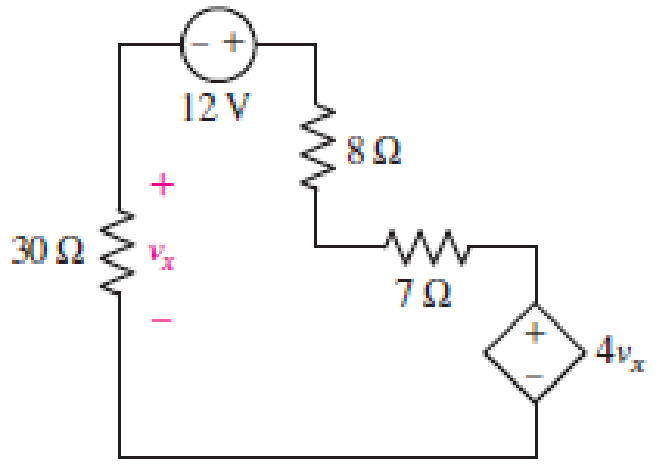
■ FIGURE 3.14 A simple loop circuit.
Expert Solution & Answer
Want to see the full answer?
Check out a sample textbook solution
Students have asked these similar questions
subject:Circuitsshow your solution please
Activity #3: How A and V placed in a circuit?
Directions: Complete the sentence by supplying the correct term in the space
provided.
The voltmeter (V) is connected in parallel with the device. The ammeter (A)
is connected in series in the circuit so that all current passing through the circuit
must pass through and be measured by the ammeter.
OF PASIG
volimeter
V
Battery
A
Resiste nce
http://armymedical.tpub.com/md0950/Placement-of-voltmeter-and-ammeter-in-circuit
NOISIAI
Q3- Compute the following equation by using a) Single loop b) No-loop
19
Mn] = EMk]x[n +k]
%3D
Chapter 3 Solutions
Loose Leaf for Engineering Circuit Analysis Format: Loose-leaf
Ch. 3.2 - 3.1 (a) Count the number of branches and nodes in...Ch. 3.3 - Determine ix and vx in the circuit of Fig. 3.7....Ch. 3.3 - For the circuit of Fig. 3.9, if vR1=1V, determine...Ch. 3.3 - Determine vx in the circuit of Fig. 3.11.Ch. 3.4 - In the circuit of Fig. 3.12b, vs1 = 120 V, vs2 =...Ch. 3.4 - 3.6 In the circuit of Fig. 3.14, find the power...Ch. 3.5 - Determine v in the circuit of Fig. 3.16.Ch. 3.5 - For the single-node-pair circuit of Fig. 3.18,...Ch. 3.6 - Determine the current i in the circuit of Fig....Ch. 3.6 - Determine the voltage v in the circuit of Fig....
Ch. 3.6 - Determine whether the circuit of Fig. 3.25...Ch. 3.7 - 3.12 Determine a single-value equivalent...Ch. 3.7 - 3.13 Determine i in the circuit of Fig. 3.29....Ch. 3.7 - Determine v in the circuit of Fig. 3.31 by first...Ch. 3.7 - 3.15 For the circuit of Fig. 3.33, calculate the...Ch. 3.8 - 3.16 Use voltage division to determine vx in the...Ch. 3.8 - In the circuit of Fig. 3.40, use resistance...Ch. 3 - Referring to the circuit depicted in Fig. 3.45,...Ch. 3 - Referring to the circuit depicted in Fig. 3.46,...Ch. 3 - For the circuit of Fig. 3.47: (a) Count the number...Ch. 3 - For the circuit of Fig. 3.47: (a) Count the number...Ch. 3 - Refer to the circuit of Fig. 3.48, and answer the...Ch. 3 - A local restaurant has a neon sign constructed...Ch. 3 - Referring to the single-node diagram of Fig. 3.50,...Ch. 3 - Determine the current labeled I in each of the...Ch. 3 - In the circuit shown in Fig. 3.52, the resistor...Ch. 3 - The circuit of Fig. 3.53 represents a system...Ch. 3 - In the circuit depicted in Fig. 3.54, ix is...Ch. 3 - For the circuit of Fig. 3.55 (which employs a...Ch. 3 - Determine the current labeled I3 in the circuit of...Ch. 3 - Study the circuit depicted in Fig. 3.57, and...Ch. 3 - Prob. 15ECh. 3 - For the circuit of Fig. 3.58: (a) Determine the...Ch. 3 - For each of the circuits in Fig. 3.59, determine...Ch. 3 - Use KVL to obtain a numerical value for the...Ch. 3 - Prob. 19ECh. 3 - In the circuit of Fig. 3.55, calculate the voltage...Ch. 3 - Determine the value of vx as labeled in the...Ch. 3 - Consider the simple circuit shown in Fig. 3.63....Ch. 3 - (a) Determine a numerical value for each current...Ch. 3 - The circuit shown in Fig. 3.65 includes a device...Ch. 3 - The circuit of Fig. 3.12b is constructed with the...Ch. 3 - Obtain a numerical value for the power absorbed by...Ch. 3 - Compute the power absorbed by each element of the...Ch. 3 - Compute the power absorbed by each element in the...Ch. 3 - Kirchhoffs laws apply whether or not Ohms law...Ch. 3 - Referring to the circuit of Fig. 3.70, (a)...Ch. 3 - Determine a value for the voltage v as labeled in...Ch. 3 - Referring to the circuit depicted in Fig. 3.72,...Ch. 3 - Determine the voltage v as labeled in Fig. 3.73,...Ch. 3 - Although drawn so that it may not appear obvious...Ch. 3 - Determine the numerical value for veq in Fig....Ch. 3 - Determine the numerical value for ieq in Fig....Ch. 3 - For the circuit presented in Fig. 3.76. determine...Ch. 3 - Determine the value of v1 required to obtain a...Ch. 3 - (a) For the circuit of Fig. 3.78, determine the...Ch. 3 - What value of IS in the circuit of Fig. 3.79 will...Ch. 3 - (a) Determine the values for IX and VY in the...Ch. 3 - Determine the equivalent resistance of each of the...Ch. 3 - For each network depicted in Fig. 3.82, determine...Ch. 3 - (a) Simplify the circuit of Fig. 3.83 as much as...Ch. 3 - (a) Simplify the circuit of Fig. 3.84, using...Ch. 3 - Making appropriate use of resistor combination...Ch. 3 - Calculate the voltage labeled vx in the circuit of...Ch. 3 - Determine the power absorbed by the 15 resistor...Ch. 3 - Calculate the equivalent resistance Req of the...Ch. 3 - Show how to combine four 100 resistors to obtain...Ch. 3 - Prob. 51ECh. 3 - Prob. 52ECh. 3 - Prob. 53ECh. 3 - Prob. 54ECh. 3 - Prob. 55ECh. 3 - Prob. 56ECh. 3 - Prob. 57ECh. 3 - Prob. 58ECh. 3 - Prob. 59ECh. 3 - Prob. 60ECh. 3 - With regard to the circuit shown in Fig. 3.98,...Ch. 3 - Delete the leftmost 10 resistor in the circuit of...Ch. 3 - Consider the seven-element circuit depicted in...
Knowledge Booster


Learn more about
Need a deep-dive on the concept behind this application? Look no further. Learn more about this topic, electrical-engineering and related others by exploring similar questions and additional content below.Similar questions
- Network 2R R 3V 2R -1.5 mA A network is implemented with three resistors and a voltage source as shown above. Its terminal characteristics are also given graphically above. From the graphical data given above, determine Thevenin equivalent voltage in volts for the network. Your Answer: Answerarrow_forwardA linear network is drawing a current I that is leading the voltage across it (Figure 3). Which statement is true about the network? I ... + Linear V Network Figure 3 (A It is resistive in nature (B It is capacitive in nature It is inductive in naturearrow_forward3. Find the applied voltage E necessary to develop the current specified in the network below. *in a simple way of solving*arrow_forward
- In the circuit of figure 3.22, R=1 ohm and i1=2A. Calculate i,i2,Vacarrow_forwardComputed (Show complete solutions and redraw as you answer) Using the circuit shown in Fig. 3. 1 and the value of the DC power supply as the theoreticalvalue of the total voltage, compute and record, total current, voltages across each resistor, and currents flowing in each resistor using Voltage and Current Divider Theorem.arrow_forward3. Research on the Thevenin's and Norton's theorem and their relations. Write those findings. 4. Derive the equation for VTH for circuit in Figure 3. 5. Derive the equation for RTH for circuit in Figure 3. 6. Derive the equation for IN for circuit in Figure 3. R6 m A 220 ohms R1 V1 R4 m 820 ohms 330 ohms 10 V R2 V2 560 ohms B R5 m vo 1 kohms 470 ohms 5 V FIGURE 3 R3arrow_forward
- Given the circuit in the Figure below, match a value to the given current (A) or voltage (V) 5 Ohms B +) IA = 0.2 A 100 Ohms 1) lB = 0.4 A 20 Ohus Current (A) through 100-Ohm resistor Choose... Voltage (V) across 5-Ohm resistor Choose... Current I_1 (A) Choose... + Choose... + Current (A) through 20-Ohm resistor Choose... Current |_3 (A) Choose... + Current I_2 (A) Choose... Voltage V_A (V) Choose... + Voltage V_B (V) Choose... wwarrow_forward6. A local restaurant has a neon sign constructed from 12 separate bulbs; when a bulb fails, it appears as an infinite resistance and cannot conduct current. In wiring the sign, the manufacturer offers two options (Fig. 3.48). From what you've learned about KCL, which one should the restaurant owner select? Еxplain. EXT\AT\RALPH'S, EAT AT RALPH'S IFIGURE 3.48 CS Scannec with CamScannerarrow_forwardDirection: Answer the following and show your solution. REFERENCE: a. Watch the video provided discussing what is current resistivity and resistance. i. Electric current - https://youtu.be/HXOok3mfMLM ii. Resistance - https://youtu.be/NfcgA1axPLo iii. Resistivity - https://youtu.be/nN3bb0aK1GM 1. Calculate the current density, resistance, and electrical field of a 5-m length of copper wire with a diameter of 2.053 mm (12-gauge) carrying a current of I=10mA.arrow_forward
- Q3. (a) Determine R,, R2 and R3, for the circuit shown in Figure Q3a. 5.6 V R1 R2 P2 = 22 mW %3D 9 V R3 10 mA Figure Q3a (b) Calculate the total current in the circuit shown in Figure Q3b. R3 560 2 R1 25 V 1.0 k2 R 4.7 k2 Figure Q3b (c) Determine the power consumed in each of the resistors of the circuit shown in Figure Q3c. 12V 20 30 Figure Q3carrow_forwardmponent of nódal ch element. There is no way of knowing the current through wever, KCL must be satisfied at a sunernode like any other node. Hence a tde spernode in Fig. 3.5, i + i4 = i2 + i3 (3.11a) v1 - v2 v1 - v3 v2 – 0 v3 - 0 (3.11b) 6. To apply Kirchhoff's voltage law to the supernode in Fig. 3.4 we redraw the circuit as shown in Fig. 3.5. Going around the loop in the clockwise»direction gives -V2 + 5 + v3 = 0=v2 – V3 = 5 (3.12) From Eqs. (3.10), (3.11b), and (3.12), we obtain the node volltages. 5V د مُسق ک من ؤ Figure 3.5 Applying KVL to a supernode. Example 3.2: For the circuit shown in Fig. 3.6, find the node voltages. Solution: The supernode contains the 2-V source, nodes 1 and 10 2 www 2, and the 10-2 resistor. Applying KCL to the 2 V supernode as shown in Fig. 3.7(a) gives 2. 12 2 = i + iz +7 7 A Expressing in and iz in terms of the node voltages 2 A 22 v1 - 0 v2 - 0 2 = 7 4 or (3.2.1) V2 =-20 - 2vVI Figure 3.6 For Example 3.2. ESTHRER: ALI SHARAAN METHORS OF ANALYSIS…arrow_forward1) For the network shown in the below figure, the value of current needs to be measured in the 10002 by connecting a 502 ammeter between two terminals A and B, find the following: a) The actual value of current. b) The measured value of current. c) The percentage error in measurement. d) The accuracy of measurement. e) Repeat the aboveif a 25002 ammeter is connected between two terminals A and B. f) State your condlusion. ww 2000 n ww 1000 A Ammeter 500 5V 20002arrow_forward
arrow_back_ios
SEE MORE QUESTIONS
arrow_forward_ios
Recommended textbooks for you
 Introductory Circuit Analysis (13th Edition)Electrical EngineeringISBN:9780133923605Author:Robert L. BoylestadPublisher:PEARSON
 Delmar's Standard Textbook Of ElectricityElectrical EngineeringISBN:9781337900348Author:Stephen L. HermanPublisher:Cengage Learning
 Programmable Logic ControllersElectrical EngineeringISBN:9780073373843Author:Frank D. PetruzellaPublisher:McGraw-Hill Education
 Fundamentals of Electric CircuitsElectrical EngineeringISBN:9780078028229Author:Charles K Alexander, Matthew SadikuPublisher:McGraw-Hill Education
 Electric Circuits. (11th Edition)Electrical EngineeringISBN:9780134746968Author:James W. Nilsson, Susan RiedelPublisher:PEARSON
 Engineering ElectromagneticsElectrical EngineeringISBN:9780078028151Author:Hayt, William H. (william Hart), Jr, BUCK, John A.Publisher:Mcgraw-hill Education,
Introductory Circuit Analysis (13th Edition)
Electrical Engineering
ISBN:9780133923605
Author:Robert L. Boylestad
Publisher:PEARSON
Delmar's Standard Textbook Of Electricity
Electrical Engineering
ISBN:9781337900348
Author:Stephen L. Herman
Publisher:Cengage Learning
Programmable Logic Controllers
Electrical Engineering
ISBN:9780073373843
Author:Frank D. Petruzella
Publisher:McGraw-Hill Education
Fundamentals of Electric Circuits
Electrical Engineering
ISBN:9780078028229
Author:Charles K Alexander, Matthew Sadiku
Publisher:McGraw-Hill Education
Electric Circuits. (11th Edition)
Electrical Engineering
ISBN:9780134746968
Author:James W. Nilsson, Susan Riedel
Publisher:PEARSON
Engineering Electromagnetics
Electrical Engineering
ISBN:9780078028151
Author:Hayt, William H. (william Hart), Jr, BUCK, John A.
Publisher:Mcgraw-hill Education,
Types of Battery | Different Types of Battery | Classification of Battery; Author: Learning Engineering;https://www.youtube.com/watch?v=Tye3dcBOqtY;License: Standard YouTube License, CC-BY