
Concept explainers
Videos
Although drawn so that it may not appear obvious at first glance, the circuit of Fig. 3.74 is in fact a single-node-pair circuit, (a) Determine the power absorbed by each resistor, (b) Determine the power supplied by each current source, (c) Show that the sum of the absorbed power calculated in (a) is equal to the sum of the supplied power calculated in (b).
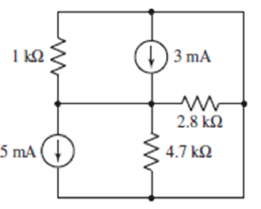
FIGURE 3.74
(a)
Find power absorbed by each resistor.
Answer to Problem 34E
Power absorbed by the resistor
Explanation of Solution
Calculation:
The circuit diagram is redrawn as shown in Figure 1.
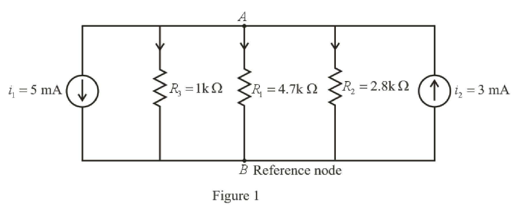
Refer to the redrawn Figure 1.
The expression for KCL at node
Here,
The expression for power absorbed by resistor is as follows.
Here,
Refer to the redrawn Figure 1.
Substitute
Rearrange equation (3) for
Substitute
Simplify for
So, power absorbed by resistor
Substitute
Simplify for
So, the power absorbed by resistor
Substitute
So, the power absorbed by resistor
Conclusion:
Thus, the power absorbed by resistor
(b)
Find the power supplied by each current source.
Answer to Problem 34E
Power supplied by dependent current source
Explanation of Solution
Formula used:
The expression for power supplied by current source is as follows.
Here,
Calculation:
Refer to the redrawn Figure 1.
As current direction for independent current source
Substitute
So power supplied by dependent current source
Substitute
So power supplied by dependent current source
Conclusion:
Thus, the power supplied by dependent current source
(c)
Verify that sum of power absorbed and sum of power supplied in the circuit is same.
Answer to Problem 34E
Sum of power absorbed and sum of power supplied in the circuit is same.
Explanation of Solution
Formula used:
The expression for power is as follows.
Here,
Calculation:
Substitute
So, the total power absorbed is
Substitute
So total power supplied is
Conclusion:
Thus, sum of power absorbed and sum of power supplied in the circuit is same.
Want to see more full solutions like this?
Chapter 3 Solutions
Loose Leaf for Engineering Circuit Analysis Format: Loose-leaf


- Design d.c voltmeter by using direct method with d'Arsonval meter of 50 2 and full scale deflection of 100 µA to give the following range :10 mV, 20 mV ,50 V. R$1 m 10 mV Im R$2 Rs3 o/p of voltmeter 1/ Rm 20 mV 50 Varrow_forward1. Two identical batteries are available. If the batteries are connected in series and a voltmeter is used to measure its terminal voltage, the voltmeter reads 18 V. If the batteries are connected in series to supply power to load R, R receives 6 A. If the batteries are connected in parallel to supply power to the same load R, R receives 10/3 A Find the Emf (E) and internal resistance (r) of each battery and the value of R.arrow_forwardThe expected value of the voltage across a resistor is 90 V. However, the measurement gives a value of 89 V. Calculate: a) Absolute Error b) Percentage Error c) Relative Accuracy d) Percentage of Accuracyarrow_forward
- Consider the circuit in Fig. 3 and perform the following: Calculate the voltage across each resistor and the current through each branch of the circuit. (Using Ohm’s law, KCL and KVL) Verify that the law of conservation of energy is satisfied by showing that the algebraic sum of power is zero.arrow_forward1. Determine the following: (a) .o be Total Current and Total LEC Power of the circuit; (b) the VA = 120 V current passing through each resistors; (c) The voltage drop across each resistors; (d) the power taken by each resistor. R = 30 2 . MERVAN P, DE MOHAMMEI I = ? R3 = 50 2 So oti 13 =? st given to the earer, for this work to be presented or R, = 40 2 LECTURE SLIDE O MEVIN ,OHAJAME SLIDE ON I PEMOHAMM R4 = 60 2 14 = ? ork to be presented or shown to others. + Rs = 60 2 shown to ohers. er, for this work to be pre Cthers. rthis work to be presented or shown R = 70 2 I6 = ? co the hown to others. 1, = ? TURE SLIDES MOHAMN R, = 80 2 CONSENT wasot given to the bearer, for this work to farrow_forwardTwo identical batteries are available. If the batteries are connected in series -aiding and a voltmeter is used to measure its terminal a) 9 V b) 0.2 Ohms c) 2.6 Ohms voltage, the voltmeter reads 18 V. If the batteries are connected in series-aiding to supply power to load R, R receives 6A. If the batteries are connected in parallel to supply power to the same load R, R receives 10/3 A. Find: (a) the EMF (E) (b) the internal resistance (r) of each battery (c) the value of load Rarrow_forward
- A workshop 100 m x 50 m is to be illuminated with intensity of illumination being 50 lux. Determine (a) the number of lamps required and (b) design a suitable scheme of lighting if coefficient of utilization = 0.9; maintenance factor = 0.7 and efficiency of lamps = 80 lm/W. Use 100-W lamps. [50 lamps]arrow_forward30 - If the voltage at the DIAC ends falls below what voltage value, it becomes an insulator?A) 25 VB) 50 VC) 65 VD) 100 VE) 200 Varrow_forward5. How do the 2 different voltmeter readings compare to each other and to the voltage predicted by circuit theory? MacBook Proarrow_forward
- TRUE OR FALSE: 1. Positive power implies that the element is supplying power. 2. Passive components are resistors, capacitors, and inductors that do not amplify or rectify. 3. All the current in the circuit passes through the ammeter must have a very high resistance. 4. If the current does not change with time, but time remains constant, we call it a direct current (DC). 5. 5hp is equivalent to 3.73kWarrow_forward1. A PMMC instrument has internal resistance of 1.7kΩ andgives full scale deflection for 50μA. Calculate the required resistance value of multiplier resistors for employing the meter as a multi range voltmeter for voltage ranges of 10V, 50V and 100V.arrow_forwardExample: Read and solve the given problems. Strictly follow the number of decimal places specified (if not specified, look at the number of decimal places in the given and follow it.) 1. Given an electrical laboratory experiment involving a series circuit with three identical resistors. The applied battery voltage measured was 9.02 V. The three resistors have the following respective voltages: Vi = 2.94V, V2 = 2.93V, and V3 = 2.96 V. Determine the following: a) The experimental total voltage based on the concept of resistances in series b) Is the value in "a" the true or the approximate value c) The true error and absolute error d) The relative true error percentarrow_forward
 Introductory Circuit Analysis (13th Edition)Electrical EngineeringISBN:9780133923605Author:Robert L. BoylestadPublisher:PEARSON
 Delmar's Standard Textbook Of ElectricityElectrical EngineeringISBN:9781337900348Author:Stephen L. HermanPublisher:Cengage Learning
 Programmable Logic ControllersElectrical EngineeringISBN:9780073373843Author:Frank D. PetruzellaPublisher:McGraw-Hill Education
 Fundamentals of Electric CircuitsElectrical EngineeringISBN:9780078028229Author:Charles K Alexander, Matthew SadikuPublisher:McGraw-Hill Education
 Electric Circuits. (11th Edition)Electrical EngineeringISBN:9780134746968Author:James W. Nilsson, Susan RiedelPublisher:PEARSON
 Engineering ElectromagneticsElectrical EngineeringISBN:9780078028151Author:Hayt, William H. (william Hart), Jr, BUCK, John A.Publisher:Mcgraw-hill Education,