
Loose Leaf for Engineering Circuit Analysis Format: Loose-leaf
9th Edition
ISBN: 9781259989452
Author: Hayt
Publisher: Mcgraw Hill Publishers
expand_more
expand_more
format_list_bulleted
Videos
Textbook Question
Chapter 3.5, Problem 8P
For the single-node-pair circuit of Fig. 3.18, Find iA, iB, and iC.
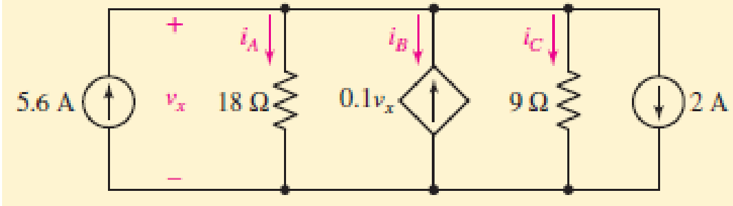
FIGURE 3.18
Expert Solution & Answer
Want to see the full answer?
Check out a sample textbook solution
Students have asked these similar questions
I want to learn how to write a Verilog gate-level description of the circuit shown in
(F) Fig. 3.25
construct th
these graphs are called
A. dots and lines
B. dots and edges
C. vertices and edges
D. vertices and lines
2. By looking at the design and aspect of ań Euler circuit, you can compare
of circuit to which of the following?
this
type
A. electrical circuit
B. robotic circuit
C. heat circuit
D. cool circuit
3. Which of the following statements appropriately discusses the process in which
vou can dotormin0 whothor a grɔnh ie an Eulor circuit or nath?
tion TM Inc.
M
Show that for a circuit with (n) nodes it is sufficient to write the
K.C.L. for (n-1) nodes and that the K.C.L. for Nth node is not
independent (support your answer with an example).
Chapter 3 Solutions
Loose Leaf for Engineering Circuit Analysis Format: Loose-leaf
Ch. 3.2 - 3.1 (a) Count the number of branches and nodes in...Ch. 3.3 - Determine ix and vx in the circuit of Fig. 3.7....Ch. 3.3 - For the circuit of Fig. 3.9, if vR1=1V, determine...Ch. 3.3 - Determine vx in the circuit of Fig. 3.11.Ch. 3.4 - In the circuit of Fig. 3.12b, vs1 = 120 V, vs2 =...Ch. 3.4 - 3.6 In the circuit of Fig. 3.14, find the power...Ch. 3.5 - Determine v in the circuit of Fig. 3.16.Ch. 3.5 - For the single-node-pair circuit of Fig. 3.18,...Ch. 3.6 - Determine the current i in the circuit of Fig....Ch. 3.6 - Determine the voltage v in the circuit of Fig....
Ch. 3.6 - Determine whether the circuit of Fig. 3.25...Ch. 3.7 - 3.12 Determine a single-value equivalent...Ch. 3.7 - 3.13 Determine i in the circuit of Fig. 3.29....Ch. 3.7 - Determine v in the circuit of Fig. 3.31 by first...Ch. 3.7 - 3.15 For the circuit of Fig. 3.33, calculate the...Ch. 3.8 - 3.16 Use voltage division to determine vx in the...Ch. 3.8 - In the circuit of Fig. 3.40, use resistance...Ch. 3 - Referring to the circuit depicted in Fig. 3.45,...Ch. 3 - Referring to the circuit depicted in Fig. 3.46,...Ch. 3 - For the circuit of Fig. 3.47: (a) Count the number...Ch. 3 - For the circuit of Fig. 3.47: (a) Count the number...Ch. 3 - Refer to the circuit of Fig. 3.48, and answer the...Ch. 3 - A local restaurant has a neon sign constructed...Ch. 3 - Referring to the single-node diagram of Fig. 3.50,...Ch. 3 - Determine the current labeled I in each of the...Ch. 3 - In the circuit shown in Fig. 3.52, the resistor...Ch. 3 - The circuit of Fig. 3.53 represents a system...Ch. 3 - In the circuit depicted in Fig. 3.54, ix is...Ch. 3 - For the circuit of Fig. 3.55 (which employs a...Ch. 3 - Determine the current labeled I3 in the circuit of...Ch. 3 - Study the circuit depicted in Fig. 3.57, and...Ch. 3 - Prob. 15ECh. 3 - For the circuit of Fig. 3.58: (a) Determine the...Ch. 3 - For each of the circuits in Fig. 3.59, determine...Ch. 3 - Use KVL to obtain a numerical value for the...Ch. 3 - Prob. 19ECh. 3 - In the circuit of Fig. 3.55, calculate the voltage...Ch. 3 - Determine the value of vx as labeled in the...Ch. 3 - Consider the simple circuit shown in Fig. 3.63....Ch. 3 - (a) Determine a numerical value for each current...Ch. 3 - The circuit shown in Fig. 3.65 includes a device...Ch. 3 - The circuit of Fig. 3.12b is constructed with the...Ch. 3 - Obtain a numerical value for the power absorbed by...Ch. 3 - Compute the power absorbed by each element of the...Ch. 3 - Compute the power absorbed by each element in the...Ch. 3 - Kirchhoffs laws apply whether or not Ohms law...Ch. 3 - Referring to the circuit of Fig. 3.70, (a)...Ch. 3 - Determine a value for the voltage v as labeled in...Ch. 3 - Referring to the circuit depicted in Fig. 3.72,...Ch. 3 - Determine the voltage v as labeled in Fig. 3.73,...Ch. 3 - Although drawn so that it may not appear obvious...Ch. 3 - Determine the numerical value for veq in Fig....Ch. 3 - Determine the numerical value for ieq in Fig....Ch. 3 - For the circuit presented in Fig. 3.76. determine...Ch. 3 - Determine the value of v1 required to obtain a...Ch. 3 - (a) For the circuit of Fig. 3.78, determine the...Ch. 3 - What value of IS in the circuit of Fig. 3.79 will...Ch. 3 - (a) Determine the values for IX and VY in the...Ch. 3 - Determine the equivalent resistance of each of the...Ch. 3 - For each network depicted in Fig. 3.82, determine...Ch. 3 - (a) Simplify the circuit of Fig. 3.83 as much as...Ch. 3 - (a) Simplify the circuit of Fig. 3.84, using...Ch. 3 - Making appropriate use of resistor combination...Ch. 3 - Calculate the voltage labeled vx in the circuit of...Ch. 3 - Determine the power absorbed by the 15 resistor...Ch. 3 - Calculate the equivalent resistance Req of the...Ch. 3 - Show how to combine four 100 resistors to obtain...Ch. 3 - Prob. 51ECh. 3 - Prob. 52ECh. 3 - Prob. 53ECh. 3 - Prob. 54ECh. 3 - Prob. 55ECh. 3 - Prob. 56ECh. 3 - Prob. 57ECh. 3 - Prob. 58ECh. 3 - Prob. 59ECh. 3 - Prob. 60ECh. 3 - With regard to the circuit shown in Fig. 3.98,...Ch. 3 - Delete the leftmost 10 resistor in the circuit of...Ch. 3 - Consider the seven-element circuit depicted in...
Knowledge Booster


Learn more about
Need a deep-dive on the concept behind this application? Look no further. Learn more about this topic, electrical-engineering and related others by exploring similar questions and additional content below.Similar questions
- a.) what is the KCL expression at node A and node B? I’m pretty sure it’s the first option for node A and option 3 for B, but I just want to make surearrow_forwardWrite a Verilog gate-level description of the circuit shown in (f) Fig. 3.25arrow_forward1.How to determine the Thevenin Equivalent circuit? What are the steps in determining the Thevenin Equivalent circuit? Give example.arrow_forward
- 9) For the network circuit below: R=1052 a)- Find is Cis V3L=10m H b): Find Z. )- Find Vh d)- Find Power e=10 sin (c283tho)arrow_forward3.68 A digital circuit is required to display a digital signal on a bar-graph LED, similar to a sound meter on a stereo. You know that the input to your circuit has values from 0 to 3 coded in binary format. You need to indicate the value in a bar graph where pro- gressively more LEDs turn on as the input number gets higher, as shown in Fig- ure 3.120. When the highest number is reached, all LEDs are on. a. Write the truth table for the circuit required to drive the LEDs. Assume that the inputs are called D₁ and Do and the outputs are Y₁, Y₂, and Y3, where Y₁ is the low- est LED in the diagram in Figure 3.120 and Y3 is the highest. Assume that the out- puts are active-HIGH. b. Write and simplify the Boolean equations for the three outputs. Draw a logic cir- cuit to show how the simplified functions can be implemented. Y₂ D₁ Do = 00 FIGURE 3.120 Problem 3.68: Bar-Graph LED 01 10 11arrow_forwardWrite a Verilog gate-level description of the circuit shown in (c) Fig. 3.21 (a) (d) Fig. 3.21 (b)arrow_forward
- I want to learn how to write a Verilog gate-level description of the circuit shown in (d) Fig. 3.21 (e) Fig. 3.24arrow_forward16. Determine the Equivalent Resistance R, for the circuit below. 3502 1002 4002 2002 12V 5002 3002 2502 502 1502arrow_forwardNETWORK LAWS Using superposition theorem: Find the contribution of current source IA to the branch current I4. IA=95 A, IB=39 A, and VA=7 V. (ANS: 63.333 A)arrow_forward
- Superposition V. Determine the current flowing through (Ix) and voltage across the 2 ohms resistor (Vx) a.) 3V acting alone a.1) Draw the circuit with 3v acting alone a.2) Solve to find Ix' and Vx' b.) 4A acting alone b.1) draw the circuit with 4A acting alone b.2) use circuit simulation software( NI Multisim, or Multisim live, or Everycircuit) simulate circuit (from b.1) and add properly ammeter and voltmeter to find Ix'' and Vx'' with 4A acting alone b.3.) Solve to find Ix'' and Vx'' (manually) c.) solve for Ix and Vx from results of (a.1, a.2, b.2) d.) simulate the original given circuit (with 3v and 4A) to check the results (from c, for Ix and Vx)arrow_forwardFind the thevenin equivalent for the portion s of the network externeal to point T and H. that is, determine the thevenin equivalent volatgearrow_forwardFind node voltages if (1) v2 reference (2) v4 reference (3) v5 reference Answer all subparts..arrow_forward
arrow_back_ios
SEE MORE QUESTIONS
arrow_forward_ios
Recommended textbooks for you
 Introductory Circuit Analysis (13th Edition)Electrical EngineeringISBN:9780133923605Author:Robert L. BoylestadPublisher:PEARSON
 Delmar's Standard Textbook Of ElectricityElectrical EngineeringISBN:9781337900348Author:Stephen L. HermanPublisher:Cengage Learning
 Programmable Logic ControllersElectrical EngineeringISBN:9780073373843Author:Frank D. PetruzellaPublisher:McGraw-Hill Education
 Fundamentals of Electric CircuitsElectrical EngineeringISBN:9780078028229Author:Charles K Alexander, Matthew SadikuPublisher:McGraw-Hill Education
 Electric Circuits. (11th Edition)Electrical EngineeringISBN:9780134746968Author:James W. Nilsson, Susan RiedelPublisher:PEARSON
 Engineering ElectromagneticsElectrical EngineeringISBN:9780078028151Author:Hayt, William H. (william Hart), Jr, BUCK, John A.Publisher:Mcgraw-hill Education,
Introductory Circuit Analysis (13th Edition)
Electrical Engineering
ISBN:9780133923605
Author:Robert L. Boylestad
Publisher:PEARSON
Delmar's Standard Textbook Of Electricity
Electrical Engineering
ISBN:9781337900348
Author:Stephen L. Herman
Publisher:Cengage Learning
Programmable Logic Controllers
Electrical Engineering
ISBN:9780073373843
Author:Frank D. Petruzella
Publisher:McGraw-Hill Education
Fundamentals of Electric Circuits
Electrical Engineering
ISBN:9780078028229
Author:Charles K Alexander, Matthew Sadiku
Publisher:McGraw-Hill Education
Electric Circuits. (11th Edition)
Electrical Engineering
ISBN:9780134746968
Author:James W. Nilsson, Susan Riedel
Publisher:PEARSON
Engineering Electromagnetics
Electrical Engineering
ISBN:9780078028151
Author:Hayt, William H. (william Hart), Jr, BUCK, John A.
Publisher:Mcgraw-hill Education,
Mesh Current Problems in Circuit Analysis - Electrical Circuits Crash Course - Beginners Electronics; Author: Math and Science;https://www.youtube.com/watch?v=DYg8B-ElK0s;License: Standard Youtube License