
Loose Leaf for Engineering Circuit Analysis Format: Loose-leaf
9th Edition
ISBN: 9781259989452
Author: Hayt
Publisher: Mcgraw Hill Publishers
expand_more
expand_more
format_list_bulleted
Concept explainers
Videos
Textbook Question
Chapter 3, Problem 24E
The circuit shown in Fig. 3.65 includes a device known as an op amp. This device has two unusual properties in the circuit shown: (1) Vd = 0 V, and (2) no current can flow into either input terminal (marked “−” and “+” inside the symbol), but it can flow through the output terminal (marked “OUT”). This seemingly impossible situation—in direct conflict with KCL—is a result of power leads to the device that are not included in the symbol. Based on this information, calculate Vout. (Hint: Two KVL equations are required, both involving the 5 V source.)
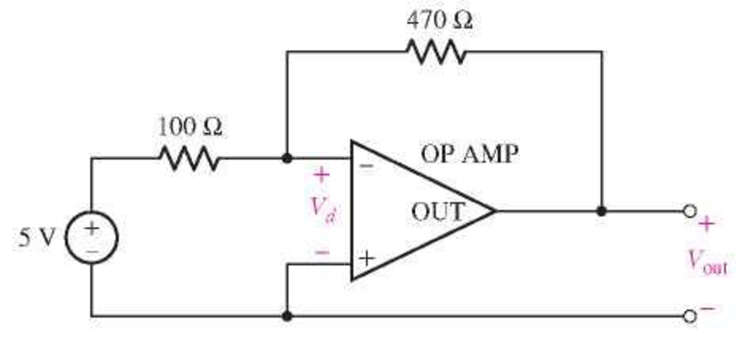
FIGURE 3.65
Expert Solution & Answer
Want to see the full answer?
Check out a sample textbook solution
Students have asked these similar questions
Question 4
Figure Q4a shows a basic current mirror structure (in its
'sink' form) which is designed to provide the current Ir at
its output Io by operating transistors Ti and T2 identically :
VDD
IR
IR
T3
T1
T2
T1
T2
OV
OV
Figure Q4a : Current Mirror
Figure Q4b : Widlaw Mirror
a)
Show that the current relationship of the circuit in figure Q4a is
( where Ic = BIb for both transistors and T1 and T2 are matched) :
IR
2
=|1+
If the two transistors in figure Q4a are not matched in terms of
b)
their Vbe's compensation can be provided by placing a resistor 'R'
in one of the emitter legs of the transistors.
Assuming Vbez > Vbel by 0.05V and Ir = Io = 10mA sketch an
appropriate structure and value for R.
c)
Describe how the 'offset' compensation referred to in Q4b
occurs in practice for a 741 op-amp ?
d)
Sketch the 'Source' form of figure Q4a
e)
Figure Q4b shows the buffered Widlar mirror. Briefly
describe how the addition of transistor T3 improves operation.
Q: For the circuit shown below, calculate the currentrsng through each resistor
for the following different input supply volta (9V, 11V,13V), then measure
these currents using Multisim applicati for the same input supply voltages
(9V, 11V,13V).
R = 100 0
IT
Vs
R4 =400 O
R3 = 300 Q
R2 = 200 0
V1
R1
V2
Da
Db
R2
www
V3
Given that R1=2k, R2=1k, and Da and Db are
Si Diodes:
a. What is V3 in terms of V1 when Da is ON?
b. What is V3 in terms of V1 when Db is ON?
c. What is V3 in terms of V1 when Da and Db
is OFF?
Chapter 3 Solutions
Loose Leaf for Engineering Circuit Analysis Format: Loose-leaf
Ch. 3.2 - 3.1 (a) Count the number of branches and nodes in...Ch. 3.3 - Determine ix and vx in the circuit of Fig. 3.7....Ch. 3.3 - For the circuit of Fig. 3.9, if vR1=1V, determine...Ch. 3.3 - Determine vx in the circuit of Fig. 3.11.Ch. 3.4 - In the circuit of Fig. 3.12b, vs1 = 120 V, vs2 =...Ch. 3.4 - 3.6 In the circuit of Fig. 3.14, find the power...Ch. 3.5 - Determine v in the circuit of Fig. 3.16.Ch. 3.5 - For the single-node-pair circuit of Fig. 3.18,...Ch. 3.6 - Determine the current i in the circuit of Fig....Ch. 3.6 - Determine the voltage v in the circuit of Fig....
Ch. 3.6 - Determine whether the circuit of Fig. 3.25...Ch. 3.7 - 3.12 Determine a single-value equivalent...Ch. 3.7 - 3.13 Determine i in the circuit of Fig. 3.29....Ch. 3.7 - Determine v in the circuit of Fig. 3.31 by first...Ch. 3.7 - 3.15 For the circuit of Fig. 3.33, calculate the...Ch. 3.8 - 3.16 Use voltage division to determine vx in the...Ch. 3.8 - In the circuit of Fig. 3.40, use resistance...Ch. 3 - Referring to the circuit depicted in Fig. 3.45,...Ch. 3 - Referring to the circuit depicted in Fig. 3.46,...Ch. 3 - For the circuit of Fig. 3.47: (a) Count the number...Ch. 3 - For the circuit of Fig. 3.47: (a) Count the number...Ch. 3 - Refer to the circuit of Fig. 3.48, and answer the...Ch. 3 - A local restaurant has a neon sign constructed...Ch. 3 - Referring to the single-node diagram of Fig. 3.50,...Ch. 3 - Determine the current labeled I in each of the...Ch. 3 - In the circuit shown in Fig. 3.52, the resistor...Ch. 3 - The circuit of Fig. 3.53 represents a system...Ch. 3 - In the circuit depicted in Fig. 3.54, ix is...Ch. 3 - For the circuit of Fig. 3.55 (which employs a...Ch. 3 - Determine the current labeled I3 in the circuit of...Ch. 3 - Study the circuit depicted in Fig. 3.57, and...Ch. 3 - Prob. 15ECh. 3 - For the circuit of Fig. 3.58: (a) Determine the...Ch. 3 - For each of the circuits in Fig. 3.59, determine...Ch. 3 - Use KVL to obtain a numerical value for the...Ch. 3 - Prob. 19ECh. 3 - In the circuit of Fig. 3.55, calculate the voltage...Ch. 3 - Determine the value of vx as labeled in the...Ch. 3 - Consider the simple circuit shown in Fig. 3.63....Ch. 3 - (a) Determine a numerical value for each current...Ch. 3 - The circuit shown in Fig. 3.65 includes a device...Ch. 3 - The circuit of Fig. 3.12b is constructed with the...Ch. 3 - Obtain a numerical value for the power absorbed by...Ch. 3 - Compute the power absorbed by each element of the...Ch. 3 - Compute the power absorbed by each element in the...Ch. 3 - Kirchhoffs laws apply whether or not Ohms law...Ch. 3 - Referring to the circuit of Fig. 3.70, (a)...Ch. 3 - Determine a value for the voltage v as labeled in...Ch. 3 - Referring to the circuit depicted in Fig. 3.72,...Ch. 3 - Determine the voltage v as labeled in Fig. 3.73,...Ch. 3 - Although drawn so that it may not appear obvious...Ch. 3 - Determine the numerical value for veq in Fig....Ch. 3 - Determine the numerical value for ieq in Fig....Ch. 3 - For the circuit presented in Fig. 3.76. determine...Ch. 3 - Determine the value of v1 required to obtain a...Ch. 3 - (a) For the circuit of Fig. 3.78, determine the...Ch. 3 - What value of IS in the circuit of Fig. 3.79 will...Ch. 3 - (a) Determine the values for IX and VY in the...Ch. 3 - Determine the equivalent resistance of each of the...Ch. 3 - For each network depicted in Fig. 3.82, determine...Ch. 3 - (a) Simplify the circuit of Fig. 3.83 as much as...Ch. 3 - (a) Simplify the circuit of Fig. 3.84, using...Ch. 3 - Making appropriate use of resistor combination...Ch. 3 - Calculate the voltage labeled vx in the circuit of...Ch. 3 - Determine the power absorbed by the 15 resistor...Ch. 3 - Calculate the equivalent resistance Req of the...Ch. 3 - Show how to combine four 100 resistors to obtain...Ch. 3 - Prob. 51ECh. 3 - Prob. 52ECh. 3 - Prob. 53ECh. 3 - Prob. 54ECh. 3 - Prob. 55ECh. 3 - Prob. 56ECh. 3 - Prob. 57ECh. 3 - Prob. 58ECh. 3 - Prob. 59ECh. 3 - Prob. 60ECh. 3 - With regard to the circuit shown in Fig. 3.98,...Ch. 3 - Delete the leftmost 10 resistor in the circuit of...Ch. 3 - Consider the seven-element circuit depicted in...
Knowledge Booster


Learn more about
Need a deep-dive on the concept behind this application? Look no further. Learn more about this topic, electrical-engineering and related others by exploring similar questions and additional content below.Similar questions
- a) find the voltage in the circuit below. b) specify whether the Op amps used in the circuit are inverted or not.arrow_forwardIn the Zener circuit shown below, calculate the Zener current IZ when VZ=10 V, E=14 V, R1=298 ohm, and R2 =298 ohm.arrow_forwardConsider the cascaded Op Amp circuit shown below. is ✓ uni 4 кл ли 10 кл M Voi un2 12 кл w -M Į t V02 1arrow_forward
- What is the output voltage in the circuit below. Refer to the following for the values: Rf = 443486 ohms, Rin = 31763 ohms, Vi = 2.7 %3D ohms. Express your answer up to two decimal places. ... 250 kn 20 k2 V = 1.5 V Round your answer to 2 decimal places.arrow_forwardMoving to another question will save this response. Quèstion 2 For the following circuit, as we increase the load resistance R, the diode current Ip increases. Ip tVD- True False A Moving to another question will save this response.arrow_forwardIn Resistive Transducer principle the resistance of a resistive element can be varied by several methods. Select one: True Falsearrow_forward
- 1. The 10M resistor (all resistor values are in Ohms and M = million) represents a scope input resistance. Calculate the voltage across the 2M resistor and compare (% error) to the ideal case. An ideal scope input resistance is the same as an ideal internal resistance of a voltmeter. 15V dc 100k 2M 10M Replace the 2M resistor with a 100K resistor and calculate the voltage across the 100K resistor and compare (% error) to the ideal case. For which resistor value (2M or 100K) does the scope have the greatest “loading” effect? Justify your answer.arrow_forwardQ3) Draw the output signal of the circuit shown in Figure 1 R1 ww 2000 R4 m 5KQ V4 R2 U1 2V 10k0 5 V1 2Vrms 1Hz 0 Figure 1 R3 m 10k0 Voutarrow_forwardDesign an op-amp circuit that can perform this operation: Vo 2V2 Draw the circuit diagram and show all the calculations as well as your assumptions. Maximum file size: 100MB, maximarrow_forward
- Can you simplify this circuit diagram because Im having a confusion how to put it in breadboard.arrow_forwardWhen OP-AMPs are considered ideal in the circuit: a) What is V voltage? b) What is the equivalent resistance of the region inside the rectangle?arrow_forwardExplain the operation of the opamp circuit in the figure. In what situations does the LED illuminate; which cases remain dim? What is the type (function) of the circuit? +12V 10K V. 10K 470 A v O -12V LEDarrow_forward
arrow_back_ios
SEE MORE QUESTIONS
arrow_forward_ios
Recommended textbooks for you
 Introductory Circuit Analysis (13th Edition)Electrical EngineeringISBN:9780133923605Author:Robert L. BoylestadPublisher:PEARSON
 Delmar's Standard Textbook Of ElectricityElectrical EngineeringISBN:9781337900348Author:Stephen L. HermanPublisher:Cengage Learning
 Programmable Logic ControllersElectrical EngineeringISBN:9780073373843Author:Frank D. PetruzellaPublisher:McGraw-Hill Education
 Fundamentals of Electric CircuitsElectrical EngineeringISBN:9780078028229Author:Charles K Alexander, Matthew SadikuPublisher:McGraw-Hill Education
 Electric Circuits. (11th Edition)Electrical EngineeringISBN:9780134746968Author:James W. Nilsson, Susan RiedelPublisher:PEARSON
 Engineering ElectromagneticsElectrical EngineeringISBN:9780078028151Author:Hayt, William H. (william Hart), Jr, BUCK, John A.Publisher:Mcgraw-hill Education,
Introductory Circuit Analysis (13th Edition)
Electrical Engineering
ISBN:9780133923605
Author:Robert L. Boylestad
Publisher:PEARSON
Delmar's Standard Textbook Of Electricity
Electrical Engineering
ISBN:9781337900348
Author:Stephen L. Herman
Publisher:Cengage Learning
Programmable Logic Controllers
Electrical Engineering
ISBN:9780073373843
Author:Frank D. Petruzella
Publisher:McGraw-Hill Education
Fundamentals of Electric Circuits
Electrical Engineering
ISBN:9780078028229
Author:Charles K Alexander, Matthew Sadiku
Publisher:McGraw-Hill Education
Electric Circuits. (11th Edition)
Electrical Engineering
ISBN:9780134746968
Author:James W. Nilsson, Susan Riedel
Publisher:PEARSON
Engineering Electromagnetics
Electrical Engineering
ISBN:9780078028151
Author:Hayt, William H. (william Hart), Jr, BUCK, John A.
Publisher:Mcgraw-hill Education,
Thevenin's Theorem; Author: Neso Academy;https://www.youtube.com/watch?v=veAFVTIpKyM;License: Standard YouTube License, CC-BY