
Loose Leaf for Engineering Circuit Analysis Format: Loose-leaf
9th Edition
ISBN: 9781259989452
Author: Hayt
Publisher: Mcgraw Hill Publishers
expand_more
expand_more
format_list_bulleted
Concept explainers
Videos
Textbook Question
Chapter 3.7, Problem 12P
3.12 Determine a single-value equivalent resistance for the network shown in Fig. 3.27, as seen between the terminals marked (a) a and b, with c unconnected; (b) a and c, with b unconnected
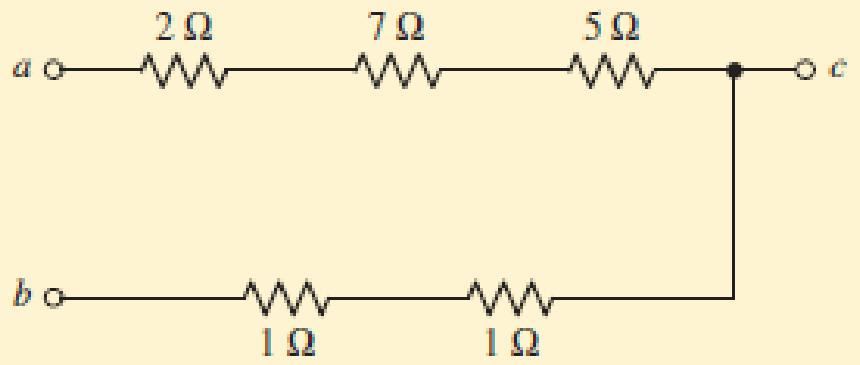
FIGURE 3.27
Expert Solution & Answer
Want to see the full answer?
Check out a sample textbook solution
Students have asked these similar questions
Fig 3.0 shows a circuitcontaining two sources of e.m.f., each with their internal resistance. Determine the current in eachbranch of the network by using the superposition
mponent of nódal
ch element. There is no way of knowing the current through
wever, KCL must be satisfied at a sunernode like any other node. Hence a tde
spernode in Fig. 3.5,
i + i4 = i2 + i3
(3.11a)
v1 - v2
v1 - v3
v2 – 0
v3 - 0
(3.11b)
6.
To apply Kirchhoff's voltage law to the supernode in Fig. 3.4 we redraw the circuit as
shown in Fig. 3.5. Going around the loop in the clockwise»direction gives
-V2 + 5 + v3 = 0=v2 – V3 = 5
(3.12)
From Eqs. (3.10), (3.11b), and (3.12), we obtain the node volltages.
5V
د مُسق ک من ؤ
Figure 3.5 Applying KVL to a supernode.
Example 3.2: For the circuit shown in Fig. 3.6, find the node voltages.
Solution:
The supernode contains the 2-V source, nodes 1 and
10 2
www
2, and the 10-2 resistor. Applying KCL to the
2 V
supernode as shown in Fig. 3.7(a) gives
2.
12
2 = i + iz +7
7 A
Expressing in and iz in terms of the node voltages
2 A
22
v1 - 0
v2 - 0
2 =
7
4
or
(3.2.1)
V2 =-20 - 2vVI
Figure 3.6 For Example 3.2.
ESTHRER: ALI SHARAAN
METHORS OF ANALYSIS…
201
1st Stage: Fundamentals of Electrical Engineering
Chapter 3- Kirchhoff's laws
2015-2016
3.3 Homework:
1- Use KCL to obtain currents i, iz, and i, in the circuit shown in below figure.
12 mA
8 mA
13
2- Find il, i2, and i3 in the circuit in Figure below,
1A
2A
3A
10 A
3- Determine v1 through v4 in the circuit in figure shown below.
12 V
- 6V
10 V
4- In the circuit in following figure, obtain v1, v2, and v3.
15 V
10 V
12
25 V
20 V
University of Thi-Qar/Department of Electrical and Electronic Engineering-Lectures are prepared by M.Sc. Ali Kareem
"Fundamentals of Electric Circuits", by: Charles K. Alexander and Matthew N. 0. Sadiku.
Page 6
Chapter 3 Solutions
Loose Leaf for Engineering Circuit Analysis Format: Loose-leaf
Ch. 3.2 - 3.1 (a) Count the number of branches and nodes in...Ch. 3.3 - Determine ix and vx in the circuit of Fig. 3.7....Ch. 3.3 - For the circuit of Fig. 3.9, if vR1=1V, determine...Ch. 3.3 - Determine vx in the circuit of Fig. 3.11.Ch. 3.4 - In the circuit of Fig. 3.12b, vs1 = 120 V, vs2 =...Ch. 3.4 - 3.6 In the circuit of Fig. 3.14, find the power...Ch. 3.5 - Determine v in the circuit of Fig. 3.16.Ch. 3.5 - For the single-node-pair circuit of Fig. 3.18,...Ch. 3.6 - Determine the current i in the circuit of Fig....Ch. 3.6 - Determine the voltage v in the circuit of Fig....
Ch. 3.6 - Determine whether the circuit of Fig. 3.25...Ch. 3.7 - 3.12 Determine a single-value equivalent...Ch. 3.7 - 3.13 Determine i in the circuit of Fig. 3.29....Ch. 3.7 - Determine v in the circuit of Fig. 3.31 by first...Ch. 3.7 - 3.15 For the circuit of Fig. 3.33, calculate the...Ch. 3.8 - 3.16 Use voltage division to determine vx in the...Ch. 3.8 - In the circuit of Fig. 3.40, use resistance...Ch. 3 - Referring to the circuit depicted in Fig. 3.45,...Ch. 3 - Referring to the circuit depicted in Fig. 3.46,...Ch. 3 - For the circuit of Fig. 3.47: (a) Count the number...Ch. 3 - For the circuit of Fig. 3.47: (a) Count the number...Ch. 3 - Refer to the circuit of Fig. 3.48, and answer the...Ch. 3 - A local restaurant has a neon sign constructed...Ch. 3 - Referring to the single-node diagram of Fig. 3.50,...Ch. 3 - Determine the current labeled I in each of the...Ch. 3 - In the circuit shown in Fig. 3.52, the resistor...Ch. 3 - The circuit of Fig. 3.53 represents a system...Ch. 3 - In the circuit depicted in Fig. 3.54, ix is...Ch. 3 - For the circuit of Fig. 3.55 (which employs a...Ch. 3 - Determine the current labeled I3 in the circuit of...Ch. 3 - Study the circuit depicted in Fig. 3.57, and...Ch. 3 - Prob. 15ECh. 3 - For the circuit of Fig. 3.58: (a) Determine the...Ch. 3 - For each of the circuits in Fig. 3.59, determine...Ch. 3 - Use KVL to obtain a numerical value for the...Ch. 3 - Prob. 19ECh. 3 - In the circuit of Fig. 3.55, calculate the voltage...Ch. 3 - Determine the value of vx as labeled in the...Ch. 3 - Consider the simple circuit shown in Fig. 3.63....Ch. 3 - (a) Determine a numerical value for each current...Ch. 3 - The circuit shown in Fig. 3.65 includes a device...Ch. 3 - The circuit of Fig. 3.12b is constructed with the...Ch. 3 - Obtain a numerical value for the power absorbed by...Ch. 3 - Compute the power absorbed by each element of the...Ch. 3 - Compute the power absorbed by each element in the...Ch. 3 - Kirchhoffs laws apply whether or not Ohms law...Ch. 3 - Referring to the circuit of Fig. 3.70, (a)...Ch. 3 - Determine a value for the voltage v as labeled in...Ch. 3 - Referring to the circuit depicted in Fig. 3.72,...Ch. 3 - Determine the voltage v as labeled in Fig. 3.73,...Ch. 3 - Although drawn so that it may not appear obvious...Ch. 3 - Determine the numerical value for veq in Fig....Ch. 3 - Determine the numerical value for ieq in Fig....Ch. 3 - For the circuit presented in Fig. 3.76. determine...Ch. 3 - Determine the value of v1 required to obtain a...Ch. 3 - (a) For the circuit of Fig. 3.78, determine the...Ch. 3 - What value of IS in the circuit of Fig. 3.79 will...Ch. 3 - (a) Determine the values for IX and VY in the...Ch. 3 - Determine the equivalent resistance of each of the...Ch. 3 - For each network depicted in Fig. 3.82, determine...Ch. 3 - (a) Simplify the circuit of Fig. 3.83 as much as...Ch. 3 - (a) Simplify the circuit of Fig. 3.84, using...Ch. 3 - Making appropriate use of resistor combination...Ch. 3 - Calculate the voltage labeled vx in the circuit of...Ch. 3 - Determine the power absorbed by the 15 resistor...Ch. 3 - Calculate the equivalent resistance Req of the...Ch. 3 - Show how to combine four 100 resistors to obtain...Ch. 3 - Prob. 51ECh. 3 - Prob. 52ECh. 3 - Prob. 53ECh. 3 - Prob. 54ECh. 3 - Prob. 55ECh. 3 - Prob. 56ECh. 3 - Prob. 57ECh. 3 - Prob. 58ECh. 3 - Prob. 59ECh. 3 - Prob. 60ECh. 3 - With regard to the circuit shown in Fig. 3.98,...Ch. 3 - Delete the leftmost 10 resistor in the circuit of...Ch. 3 - Consider the seven-element circuit depicted in...
Knowledge Booster


Learn more about
Need a deep-dive on the concept behind this application? Look no further. Learn more about this topic, electrical-engineering and related others by exploring similar questions and additional content below.Similar questions
- In the circuits of Fig. 3.2a and b, what aspects of Ohm’s law were validated?arrow_forwardFind fis for below network (express your answer in hertz, no unit, and round-off up to two decimal places). Refer to the image for the network but refer to these for the values of: VCC = 18 V, R1 = 162725 ohms, R2 = 38951 ohms, RE = 4097 ohms, RL = 12748 ohms, beta = 123, Cs = 0.0002 F, Ce = 0.0002 F, Zi = 81.31 ohms Also, approximate IE as (beta + 1) Ib. 14 V C = 8 pF Csc = 20 pF 30 pF 10 pl Che 120 k2 C 12 pF B = 100 0.1 µF 0.1 µF C9 30 kl2 2.2 k2 8.2 k2arrow_forwardQ3- Compute the following equation by using a) Single loop b) No-loop 19 Mn] = EMk]x[n +k] %3Darrow_forward
- Computed (Show complete solutions.) Using the circuit shown in Fig. 3. 1 and the value of the DC power supply as the theoreticalvalue of the total voltage, compute and record, total current, voltages across each resistor, andcurrents flowing in each resistor using Voltage and Current Divider Theorem.arrow_forwardQ2/ Find the state-space representation of the electrical network shown in Figure 3.8. The output is vo(t). C₁ R не Vo(1) L 0000arrow_forward1) For the network shown in the below figure, the value of current needs to be measured in the 10002 by connecting a 502 ammeter between two terminals A and B, find the following: a) The actual value of current. b) The measured value of current. c) The percentage error in measurement. d) The accuracy of measurement. e) Repeat the aboveif a 25002 ammeter is connected between two terminals A and B. f) State your condlusion. ww 2000 n ww 1000 A Ammeter 500 5V 20002arrow_forward
- 3.16 Eliminate the exclusive-OR, and then factor to obtain a minimum product of sums: (a) (KL + M) + M'N' (b) M'(K + N') + MN + K'Narrow_forwardQ3) For the network shown in the figure below, determine the following: a) fe b) Zinl and Zin2 c) Zo1 and Zo2 d) Avı, Av2, and AVT +20 V 6.8 kQ 30 ka 6.8 ka 30 ka 0.5 F 0.5 uF P-150 B- 150 1.5 ka 50 uF 1.5 ka 50 uFarrow_forward3. Research on the Thevenin's and Norton's theorem and their relations. Write those findings. 4. Derive the equation for VTH for circuit in Figure 3. 5. Derive the equation for RTH for circuit in Figure 3. 6. Derive the equation for IN for circuit in Figure 3. R6 m A 220 ohms R1 V1 R4 m 820 ohms 330 ohms 10 V R2 V2 560 ohms B R5 m vo 1 kohms 470 ohms 5 V FIGURE 3 R3arrow_forward
- For the network in Fig. 3.6, establish a measurement model considering:(a) PI2 and P I 3 as state variables; (b) PI and P3 as state variables. Comparethe results with those obtained for Example 3.6. Discuss the pros and consof each of the three choices of state variables. Detailed answer is needed.arrow_forwardIn the circuit of figure 3.24 a) calculate the input resistance seen by the voltage source R input= v/i, as a function of a and b) calculate R input for a=0, 1 , 2 answers: a) R input= R/(1-a) b) R, infinity, -Rarrow_forwardElectrical Engineering For the final problem, consider the following circuit diagram: 12 Q 30 V Vx 60 Q 2"Vx B 6) For this circuit, please find and draw: a. The Thevenin equivalent circuit between A and B, using external excitation to find R. b. The Norton cquivalent circuit berween A and B. c. Review section 3-8 from the text. What value load resistor connected between A and B would yield maximum power transfer? How much power woukd this be?arrow_forward
arrow_back_ios
SEE MORE QUESTIONS
arrow_forward_ios
Recommended textbooks for you
 Introductory Circuit Analysis (13th Edition)Electrical EngineeringISBN:9780133923605Author:Robert L. BoylestadPublisher:PEARSON
 Delmar's Standard Textbook Of ElectricityElectrical EngineeringISBN:9781337900348Author:Stephen L. HermanPublisher:Cengage Learning
 Programmable Logic ControllersElectrical EngineeringISBN:9780073373843Author:Frank D. PetruzellaPublisher:McGraw-Hill Education
 Fundamentals of Electric CircuitsElectrical EngineeringISBN:9780078028229Author:Charles K Alexander, Matthew SadikuPublisher:McGraw-Hill Education
 Electric Circuits. (11th Edition)Electrical EngineeringISBN:9780134746968Author:James W. Nilsson, Susan RiedelPublisher:PEARSON
 Engineering ElectromagneticsElectrical EngineeringISBN:9780078028151Author:Hayt, William H. (william Hart), Jr, BUCK, John A.Publisher:Mcgraw-hill Education,
Introductory Circuit Analysis (13th Edition)
Electrical Engineering
ISBN:9780133923605
Author:Robert L. Boylestad
Publisher:PEARSON
Delmar's Standard Textbook Of Electricity
Electrical Engineering
ISBN:9781337900348
Author:Stephen L. Herman
Publisher:Cengage Learning
Programmable Logic Controllers
Electrical Engineering
ISBN:9780073373843
Author:Frank D. Petruzella
Publisher:McGraw-Hill Education
Fundamentals of Electric Circuits
Electrical Engineering
ISBN:9780078028229
Author:Charles K Alexander, Matthew Sadiku
Publisher:McGraw-Hill Education
Electric Circuits. (11th Edition)
Electrical Engineering
ISBN:9780134746968
Author:James W. Nilsson, Susan Riedel
Publisher:PEARSON
Engineering Electromagnetics
Electrical Engineering
ISBN:9780078028151
Author:Hayt, William H. (william Hart), Jr, BUCK, John A.
Publisher:Mcgraw-hill Education,
Current Divider Rule; Author: Neso Academy;https://www.youtube.com/watch?v=hRU1mKWUehY;License: Standard YouTube License, CC-BY