
Loose Leaf for Engineering Circuit Analysis Format: Loose-leaf
9th Edition
ISBN: 9781259989452
Author: Hayt
Publisher: Mcgraw Hill Publishers
expand_more
expand_more
format_list_bulleted
Videos
Textbook Question
Chapter 3, Problem 61E
With regard to the circuit shown in Fig. 3.98, compute (a) the voltage across the two 10 Ω resistors, assuming the top terminal is the positive reference, and (b) the power dissipated by the 47 Ω resistor. (c) If the maximum rating of the 47 Ω resistor is 0.25 W, is it exceeded by this circuit? Explain.
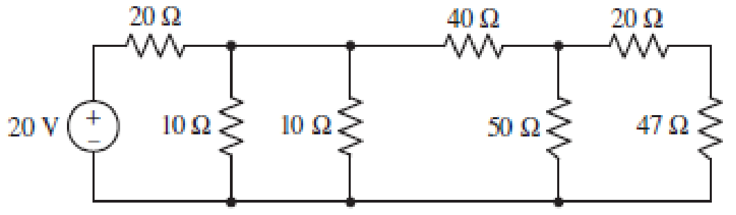
■ FIGURE 3.98
Expert Solution & Answer
Want to see the full answer?
Check out a sample textbook solution
Students have asked these similar questions
Q3)
A) Find RAB for the circuit shown in Figure 3.
A O
4 N
50
Figure 3
Q3)
A) Find Ras for the circuit shown in Figure 3.
50
Figure 3
B) For the circuit shown in Figure 4, use the superposition theorem, the voltage
divider rule and the current divider rule to find in.
30
sn Ov
2 V
Figure 4
Components Used:
Part
Values
R1
1.5 KΩ
R2
400 Ω
R3
500 Ω
VS1
8.5 V
VS2
4 V
complete the table
Chapter 3 Solutions
Loose Leaf for Engineering Circuit Analysis Format: Loose-leaf
Ch. 3.2 - 3.1 (a) Count the number of branches and nodes in...Ch. 3.3 - Determine ix and vx in the circuit of Fig. 3.7....Ch. 3.3 - For the circuit of Fig. 3.9, if vR1=1V, determine...Ch. 3.3 - Determine vx in the circuit of Fig. 3.11.Ch. 3.4 - In the circuit of Fig. 3.12b, vs1 = 120 V, vs2 =...Ch. 3.4 - 3.6 In the circuit of Fig. 3.14, find the power...Ch. 3.5 - Determine v in the circuit of Fig. 3.16.Ch. 3.5 - For the single-node-pair circuit of Fig. 3.18,...Ch. 3.6 - Determine the current i in the circuit of Fig....Ch. 3.6 - Determine the voltage v in the circuit of Fig....
Ch. 3.6 - Determine whether the circuit of Fig. 3.25...Ch. 3.7 - 3.12 Determine a single-value equivalent...Ch. 3.7 - 3.13 Determine i in the circuit of Fig. 3.29....Ch. 3.7 - Determine v in the circuit of Fig. 3.31 by first...Ch. 3.7 - 3.15 For the circuit of Fig. 3.33, calculate the...Ch. 3.8 - 3.16 Use voltage division to determine vx in the...Ch. 3.8 - In the circuit of Fig. 3.40, use resistance...Ch. 3 - Referring to the circuit depicted in Fig. 3.45,...Ch. 3 - Referring to the circuit depicted in Fig. 3.46,...Ch. 3 - For the circuit of Fig. 3.47: (a) Count the number...Ch. 3 - For the circuit of Fig. 3.47: (a) Count the number...Ch. 3 - Refer to the circuit of Fig. 3.48, and answer the...Ch. 3 - A local restaurant has a neon sign constructed...Ch. 3 - Referring to the single-node diagram of Fig. 3.50,...Ch. 3 - Determine the current labeled I in each of the...Ch. 3 - In the circuit shown in Fig. 3.52, the resistor...Ch. 3 - The circuit of Fig. 3.53 represents a system...Ch. 3 - In the circuit depicted in Fig. 3.54, ix is...Ch. 3 - For the circuit of Fig. 3.55 (which employs a...Ch. 3 - Determine the current labeled I3 in the circuit of...Ch. 3 - Study the circuit depicted in Fig. 3.57, and...Ch. 3 - Prob. 15ECh. 3 - For the circuit of Fig. 3.58: (a) Determine the...Ch. 3 - For each of the circuits in Fig. 3.59, determine...Ch. 3 - Use KVL to obtain a numerical value for the...Ch. 3 - Prob. 19ECh. 3 - In the circuit of Fig. 3.55, calculate the voltage...Ch. 3 - Determine the value of vx as labeled in the...Ch. 3 - Consider the simple circuit shown in Fig. 3.63....Ch. 3 - (a) Determine a numerical value for each current...Ch. 3 - The circuit shown in Fig. 3.65 includes a device...Ch. 3 - The circuit of Fig. 3.12b is constructed with the...Ch. 3 - Obtain a numerical value for the power absorbed by...Ch. 3 - Compute the power absorbed by each element of the...Ch. 3 - Compute the power absorbed by each element in the...Ch. 3 - Kirchhoffs laws apply whether or not Ohms law...Ch. 3 - Referring to the circuit of Fig. 3.70, (a)...Ch. 3 - Determine a value for the voltage v as labeled in...Ch. 3 - Referring to the circuit depicted in Fig. 3.72,...Ch. 3 - Determine the voltage v as labeled in Fig. 3.73,...Ch. 3 - Although drawn so that it may not appear obvious...Ch. 3 - Determine the numerical value for veq in Fig....Ch. 3 - Determine the numerical value for ieq in Fig....Ch. 3 - For the circuit presented in Fig. 3.76. determine...Ch. 3 - Determine the value of v1 required to obtain a...Ch. 3 - (a) For the circuit of Fig. 3.78, determine the...Ch. 3 - What value of IS in the circuit of Fig. 3.79 will...Ch. 3 - (a) Determine the values for IX and VY in the...Ch. 3 - Determine the equivalent resistance of each of the...Ch. 3 - For each network depicted in Fig. 3.82, determine...Ch. 3 - (a) Simplify the circuit of Fig. 3.83 as much as...Ch. 3 - (a) Simplify the circuit of Fig. 3.84, using...Ch. 3 - Making appropriate use of resistor combination...Ch. 3 - Calculate the voltage labeled vx in the circuit of...Ch. 3 - Determine the power absorbed by the 15 resistor...Ch. 3 - Calculate the equivalent resistance Req of the...Ch. 3 - Show how to combine four 100 resistors to obtain...Ch. 3 - Prob. 51ECh. 3 - Prob. 52ECh. 3 - Prob. 53ECh. 3 - Prob. 54ECh. 3 - Prob. 55ECh. 3 - Prob. 56ECh. 3 - Prob. 57ECh. 3 - Prob. 58ECh. 3 - Prob. 59ECh. 3 - Prob. 60ECh. 3 - With regard to the circuit shown in Fig. 3.98,...Ch. 3 - Delete the leftmost 10 resistor in the circuit of...Ch. 3 - Consider the seven-element circuit depicted in...
Knowledge Booster


Learn more about
Need a deep-dive on the concept behind this application? Look no further. Learn more about this topic, electrical-engineering and related others by exploring similar questions and additional content below.Similar questions
- n Figure 8, E, =18.0 V, r= 0.2 N, R¡ = 8.0 N and R3= 12.0 N. Determine the current and the voltage for element of the circuit. See the table below. %3D R 24 N R2arrow_forwarda) Using the circuit schematic, find a set of three equations that will allow you to solve for the three currents. b) What are the currents if Ԑ1=28 V, Ԑ2=9 V, R1=177 Ω, R2=293 Ω, R3=326 Ω, and R4=104 Ω. ? To continue, please enter the result of I3 in units of A. Round your answer to 3 decimal placesarrow_forwardplease solve the following problem. the thevenen equivalent values should be 12v and 4 ohms. And then the current determined by the Norton equivalent should be 2A. thank you! Please typing format answerarrow_forward
- ! Required information The given circuit consists of a voltage source of Vx= 2.200 V and a current source of 1 A. 292 www V₂ (+) 202. 292 A. 1 A Using superposition to consider each source one at a time, compute ix. (Round the final answer to three decimal places.) The value of ix isarrow_forwardRequired information The figure shows a simplified circuit diagram for an automobile. The equivalent resistor R represents the total electrical load due to spark plugs, lights, radio, fans, starter, rear window defroster, and the like in parallel. Alternator Battery 14.0 V R₁ 12.0 V R₂ R where R₁ = 94.0 m2 and R₂ = 41.0 m2. What is the terminal voltage of the battery?arrow_forwardIn the circuit shown below, the voltage at node X can be expressed in the form X = al + bV, where I and V are the source values. Use the superposition principle to determine the values of a and b. [Your answers should be rounded to 2 decimal places. Please use a full stop to indicate a decimal point.] 2Ω Numerical Answer for a (V/A) Numerical Answer for b (V/N)arrow_forward
- Calculate : a) Total resistance, RT b) T otal current ,IT from the source c) Current through resistor R3arrow_forwardb) Forthenetwork shownin the belowfigure, a voltmeter is connected across terminals A and B. The voltmeter has a resistance of 1.5k2, find the following: 1) The reading ofthe voltmeter under an open circuit. 2) Thereading ofvoltmeter under loaded condition. 3) Theloading eror. 4) The accuracy ofmeasurement. XMM4 R1 R4 5000 10000 R2 10000 V1 10V R3 5000arrow_forward3. Determine Vo and ID for the networks of figure. (3 Decimal Places, express your answer in milli) Attached your completion solution, no point will be given without the solutions. V3 Si4 Vo 15V R4 5k2arrow_forward
- Q3// i) Find the total energy stored in the circuit of Figure 3. 2H 3 H 12 V 6 A 2F Figure 3arrow_forwardYou are given a galvanometer with a resistance of 16.3 2 and a full scale deflection current of 8.22 mA. You use a 22.7-mN shunt resistor to convert this galvanometer into an ammeter. (a) How should you connect the shunt resistor and galvanometer resistance? series parallel (b) Find the maximum current the ammeter is capable of reading. Aarrow_forwardo 2-F) Given the following circuit, with R = 24k2, R = 11 k52, Rs = 36k52, Vin = 8V, and defined current directions, find: (show the details of your work) a) the current through R₁ b) the voltage across R2 c) the current through Ra R₁ www हीन R₂₂ R3 Voutarrow_forward
arrow_back_ios
SEE MORE QUESTIONS
arrow_forward_ios
Recommended textbooks for you
 Introductory Circuit Analysis (13th Edition)Electrical EngineeringISBN:9780133923605Author:Robert L. BoylestadPublisher:PEARSON
 Delmar's Standard Textbook Of ElectricityElectrical EngineeringISBN:9781337900348Author:Stephen L. HermanPublisher:Cengage Learning
 Programmable Logic ControllersElectrical EngineeringISBN:9780073373843Author:Frank D. PetruzellaPublisher:McGraw-Hill Education
 Fundamentals of Electric CircuitsElectrical EngineeringISBN:9780078028229Author:Charles K Alexander, Matthew SadikuPublisher:McGraw-Hill Education
 Electric Circuits. (11th Edition)Electrical EngineeringISBN:9780134746968Author:James W. Nilsson, Susan RiedelPublisher:PEARSON
 Engineering ElectromagneticsElectrical EngineeringISBN:9780078028151Author:Hayt, William H. (william Hart), Jr, BUCK, John A.Publisher:Mcgraw-hill Education,
Introductory Circuit Analysis (13th Edition)
Electrical Engineering
ISBN:9780133923605
Author:Robert L. Boylestad
Publisher:PEARSON
Delmar's Standard Textbook Of Electricity
Electrical Engineering
ISBN:9781337900348
Author:Stephen L. Herman
Publisher:Cengage Learning
Programmable Logic Controllers
Electrical Engineering
ISBN:9780073373843
Author:Frank D. Petruzella
Publisher:McGraw-Hill Education
Fundamentals of Electric Circuits
Electrical Engineering
ISBN:9780078028229
Author:Charles K Alexander, Matthew Sadiku
Publisher:McGraw-Hill Education
Electric Circuits. (11th Edition)
Electrical Engineering
ISBN:9780134746968
Author:James W. Nilsson, Susan Riedel
Publisher:PEARSON
Engineering Electromagnetics
Electrical Engineering
ISBN:9780078028151
Author:Hayt, William H. (william Hart), Jr, BUCK, John A.
Publisher:Mcgraw-hill Education,
[1.2] 8086 Microprocessor Architecture; Author: ThinkX Academy;https://www.youtube.com/watch?v=XX9rDGTBGgQ;License: Standard Youtube License