
Concept explainers
Videos
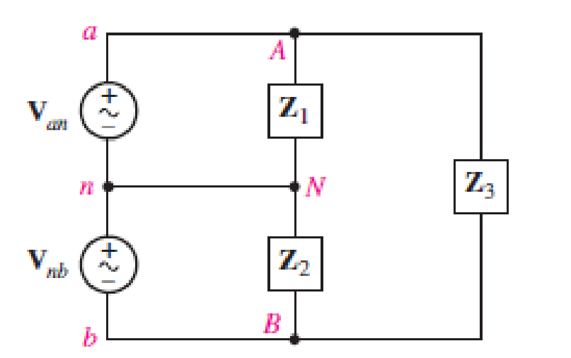
The single-phase three-wire system of Fig. 12.31 has three separate load impedances. If the source is balanced and Van = 110 +j0 V rms, (a) express Van and Vbn in phasor notation. (b) Determine the phasor voltage which appears across the impedance Z3. (c) Determine the average power delivered by the two sources if Z1 = 50 + j0 Ω, Z2 = 100 + j45 Ω, and Z3 = 100 – j90 Ω. (d) Represent load Z3 by a series connection of two elements, and state their respective values if the sources operate at 60 Hz.
(a)
The expression of phase to neutral voltage of phase
Answer to Problem 11E
The expression of phase to neutral voltage of phase
Explanation of Solution
Given data:
The phase to neutral voltage of phase
Calculation:
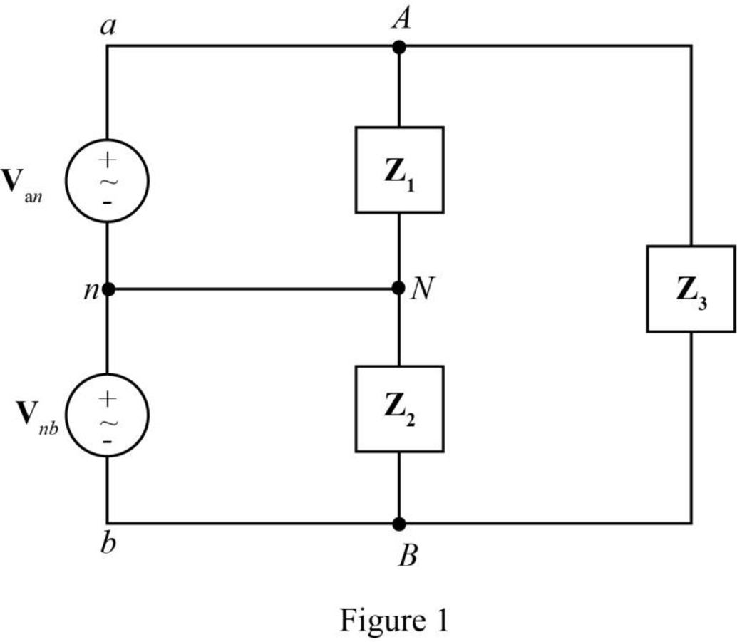
The given diagram is shown in Figure 1.
The general expression for the phasor notation is given by,
Here,
The magnitude of
Here,
The angle measured from the reference
Substitute
Substitute
Substitute
The voltage
The voltage
Substitute
Substitute
Conclusion:
Therefore, the expression of phase to neutral voltage of phase
(b)
The phasor voltage which appears across the impedance
Answer to Problem 11E
The phasor voltage which appears across the impedance
Explanation of Solution
Calculation:
The voltage across the impedance
The voltage across the impedance
The voltage across the impedance
The voltage across the impedance
Substitute
Conclusion:
Therefore, the phasor voltage which appears across the impedance
(c)
The average power delivered by the two sources.
Answer to Problem 11E
The average power delivered by source
Explanation of Solution
Given data:
The value of the impedance
The value of the impedance
The value of the impedance
Calculation:
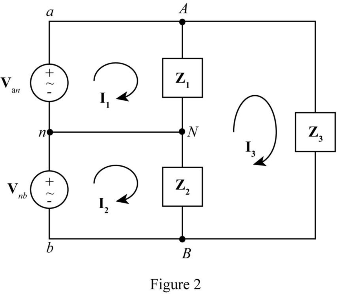
The required diagram is shown in Figure 2.
The formula to find current
Substitute
Substitute
Substitute
Substitute
The formula to find current
Substitute
Substitute
Substitute
Substitute
The formula to find current
Substitute
The power
Substitute
The power
Substitute
Conclusion:
Therefore, the average power delivered by source
(d)
The representation of load
Answer to Problem 11E
The impedance
Explanation of Solution
Given data:
The operating frequency is
Calculation:
The value of the impedance
The real part of
Hence, the resistance
The imaginary part of
Hence, The series capacitive reactance
Here,
Substitute
Conclusion:
Therefore, the impedance
Want to see more full solutions like this?
Chapter 12 Solutions
Loose Leaf for Engineering Circuit Analysis Format: Loose-leaf


- a. Y-Connected b. В 100kW Source 0.9 LAG 80KVA 0.8 LAG Figure 1 80kW 0.85 LAGarrow_forwardChoose the correct answer: Capacitors in AC circuits dissipate power in the form of heat Select one: O True O False Choose the correct answer: In a balanced three-phase system, phase shift between phase and line voltage is 30". Select one: O True O False What is the phase shift between a phase current and its voltage in a three-phase balanced system? O a. 90 O b. It can be anything, it depends on system parameters. O C. 120 Od 30°arrow_forward2. A single-phase a.c. distributor AB is fed from end A and has a total impedance of (0-2 + j 03) ohm. At the far end, the voltage V = 240 V and the current is 100 A at a p.f. of 0-8 lagging. At the mid-point M, a current of 100 A is tapped at a p.f. of 0-6 lagging with reference to the voltage Vy at the mid-point. Calculate the supply voltage V, and phase angle between V, and Vg- [292 V, 2-6°] a loadearrow_forward
- 1. What is the main direct cause of reactive power in AC system? A. Resistance of transmission lines B. Inductance and capacitance in the loads C. Ideal transformer connected in the system D. Power produced by generator 2. "Reactive power in a system is dissipated generally as thermal energy?" A. TRUE B. FALSE 3. Which of the following statements are correct for three phase circuit: A. Sum of all the three phase currents is zero in unbalanced network B. Total power transfer to load is constant with time C. Neutral conductor is same size in terms of material used as in single phase conductors D. Net apparent power consumed is equal to real powerarrow_forward5. The figure below shows two star connected loads with three phase power. The voltage source is 120Z0°. The loads are Z₁ = 10 + j4 № and Z₂ = 2 +j3 №. The cables are negligible. Calculate: a) the line and phase current. b) the real power from the source. c) the reactive power of the circuit. Is V N Z₁ Z₁ Z₁ Z₂ Z₂ N N Z₂arrow_forwardA load of 138+j460 Ohm is supplied through 3+j14 Ohm line as shown in Figure 1. (a) Find the average power dissipated in the line. (b) Find the value of capacitive reactance connected across the load to compensate the reactive power need of the load. (c) What is the equivalent impedance after compensation. (d) Find the average power dissipated in the line when the capacitive reactance is connected across the load. (e) Express the power loss in (d) as a percentage of the power found in (a) j14 Figure 1 7200/0 + V (rms) Source 3 wi Line Load 138 j460arrow_forward
- 2.42 A balanced A-connected impedance load with (12 + j9) N per phase is supplied by a balanced three-phase 60-Hz, 208-V source, (a) Calculate the line current, the total real and reactive power absorbed by the load, the load power factor, and the apparent load power, (b) Sketch a phasor diagram showing the line currents, the line-to-line source voltages, and the A-load currents. Use Vah as the reference.arrow_forward1. Two impedances, Z1 =5230• ohms and Z2 = 10445• ohms, draw a current of 3.36 A when connected in series to a certain a.c. supply. Determine (a) the supply voltage, (b) the phase angle between the voltage and current, (c) the p.d. across Z1 and (d) the p.d. across Z2arrow_forwardWhich of the following descriptions IS NOT correct for loads in power systems? A. The purely resistive load absorbs the real power from the power grid B. The purely inductive load absorbs the positive reactive power from the power grid C. The purely capacitive load absorbs the positive reactive power from the power grid. D. The average value of the instantaneous power through loads is equal to its real power. In an ac circuit, power factor correction or improvement is achieved by A. Connecting a resistor in parallel with the inductive load B. Connecting an inductor in parallel with the inductive load C. Connecting a capacitor in parallel with the inductive load A balanced delta-load can be converted to an cquivalent balanced wye- load by dividing the delta-load impedance by A. square root of 3 В.3 C. 1/3arrow_forward
- 12. A certain load takes 300 kW at 400 V. A three phase capacitor bank rated 15 kVA per phase is connected in parallel with the load to raise the power factor of the system to 90% lagging. What is the power factor of the load before correction? c. 92% d. 88% a. 99% b. 95% 13. A 132 kV line three phase system delivers 70.7 MVA on a balanced delta connected load of a power factor 70.7% lagging. Determine the reactance necessary to attain unity power factor. a. 1 092 ohms c. 1142 ohms d. 1 045 ohms b. 965 ohms 14. A 150 kVA transformer bank will serve a load expected to draw 135 kW at 0.80 lagging power factor. Solve for the size of the capacitor bank needed to be added in order to prevent overloading of the transformer bank. a 40.391 KVAR d. 28.266 KVAR a. 32.506 KVAR b. 35.866 KVARarrow_forwardTwo delta connected loads are connected in parallel and powered by a balanced Y-connectedsource. The smaller of two loads draws 10 kVA at a lagging power factor of 0.75 and the largerdraws 25 kVA at a leading power factor of 0.8. The line voltage is 400 V. Calculate a) The powerfactor at which the source is operating. b) The total power drawn by the two loads. c) The phasecurrent of each load.arrow_forwardObtain the equivalent circuit of a 200/400 V, 50 Hz, single-phase transformcr from the following test data: O.C. test : 200 V, 0-7 A, 70 W .. on L.V. side S.C. test : 15 V, 10 A, 85 W Calculate the secondary voltage when delivering S kW at 08 p.f. lagging, the primary voltage being . on H.V. side 200 V. (R, = 57-14 Q ; X, = 330 2; R = 0-21 Q ; Xg, = 0-31 Q ; 3778 V)arrow_forward
 Introductory Circuit Analysis (13th Edition)Electrical EngineeringISBN:9780133923605Author:Robert L. BoylestadPublisher:PEARSON
 Delmar's Standard Textbook Of ElectricityElectrical EngineeringISBN:9781337900348Author:Stephen L. HermanPublisher:Cengage Learning
 Programmable Logic ControllersElectrical EngineeringISBN:9780073373843Author:Frank D. PetruzellaPublisher:McGraw-Hill Education
 Fundamentals of Electric CircuitsElectrical EngineeringISBN:9780078028229Author:Charles K Alexander, Matthew SadikuPublisher:McGraw-Hill Education
 Electric Circuits. (11th Edition)Electrical EngineeringISBN:9780134746968Author:James W. Nilsson, Susan RiedelPublisher:PEARSON
 Engineering ElectromagneticsElectrical EngineeringISBN:9780078028151Author:Hayt, William H. (william Hart), Jr, BUCK, John A.Publisher:Mcgraw-hill Education,