
Concept explainers
Videos
Repeat Exercise 17 with Rw = 10 Ω, and verify your answers with an appropriate set of simulations if the operating frequency is 60 Hz.
Assume the system shown in Fig. 12.34 is balanced, Rw = 0, Van = 208∠0° V, and a positive phase sequence applies. Calculate all phase and line currents, and all phase and line voltages, if Zp is equal to (a) 1 kΩ; (b) 100 + j48 Ω; (c) 100 − j48 Ω.
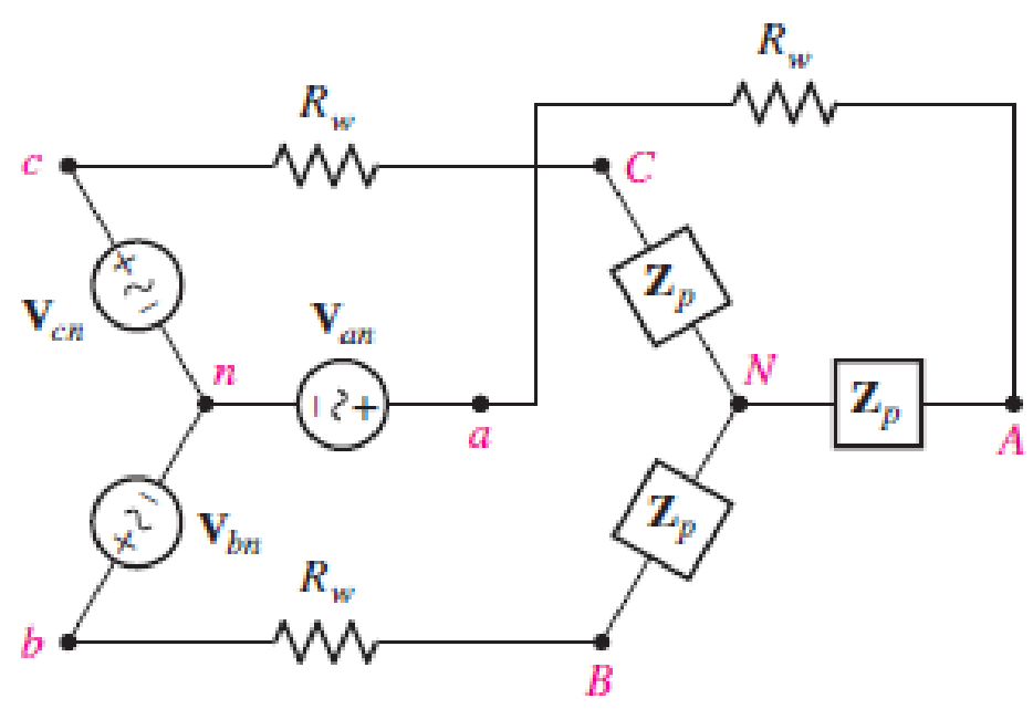
■ FIGURE 12.34
(a)
Find the line and phase currents, line and phase voltages at the load when the load impedance
Answer to Problem 18E
The line and phase currents are
Explanation of Solution
Given data:
The line resistance
The load impedance
The source phase voltage is
The simulation operation frequency is
LTspice Simulation:
Draw the given circuit diagram as shown in Figure 1, where 1, 2, and 3 are placed for node representations using Label Net.
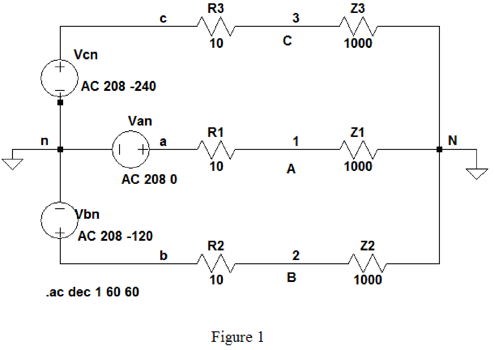
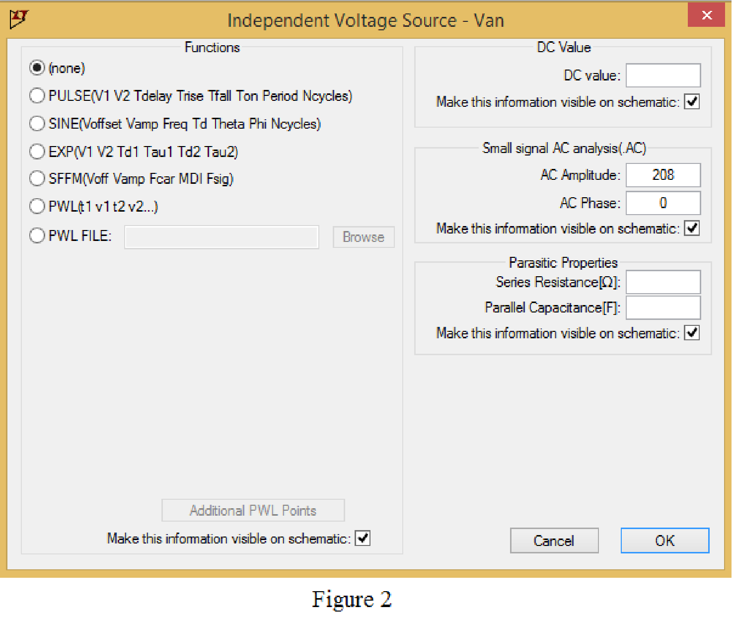
Set the values of voltages Van, Vbn and Vcn by right clicking on the voltage component, select none in “Functions” and enter the Small signal AC analysis parameters: AC amplitude as 208 and AC phase as 0 for V1, and enter other two voltage values accordingly positive phase sequence as shown in Figure 2 for V1.
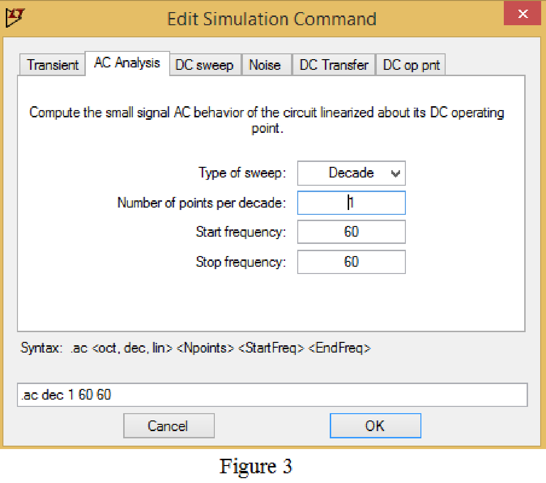
Now save the circuit, and open the “Edit Simulation command” choose AC analysis and select the sweep type as Decade, Number of points per decade 1, Start frequency and Stop frequency as 60 Hz shown in Figure 3.
Now, run the simulation for the designed circuit. The output for the AC analysis will displays as shown in Figure 4.
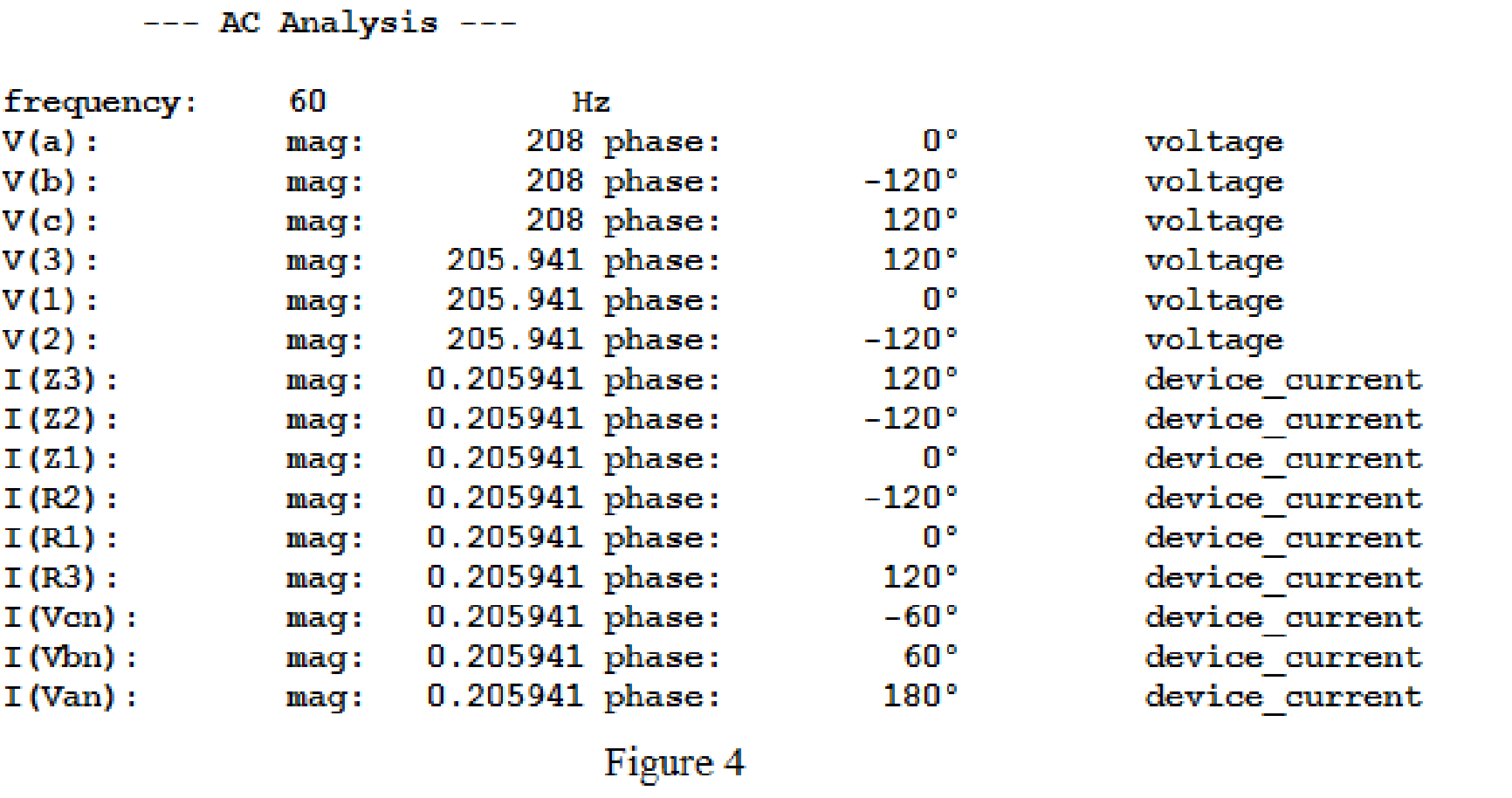
For the wye-wye connection, phase currents and line currents are equal and they are equals to
Then,
In above simulation results, the phase voltages at the load
Then, the phase voltages at the load are,
The magnitude of the phase voltages is
Write the formula to find the line voltage
Substitute
Write the formula to find the line voltage
Substitute
Write the formula to find the line voltage
Substitute
Conclusion:
Thus, the line and phase currents are
(b)
Find the line and phase currents, line and phase voltages at the load when the load impedance
Answer to Problem 18E
The line and phase currents are
The phase voltages are
Explanation of Solution
Given data:
Refer to part (a).
LTspice Simulation:
The load impedance is given as,
Where load resistance is
Write the formula to find the inductive reactance as follows.
Substitute
Draw the given circuit diagram as shown in Figure 5 for the load impedance
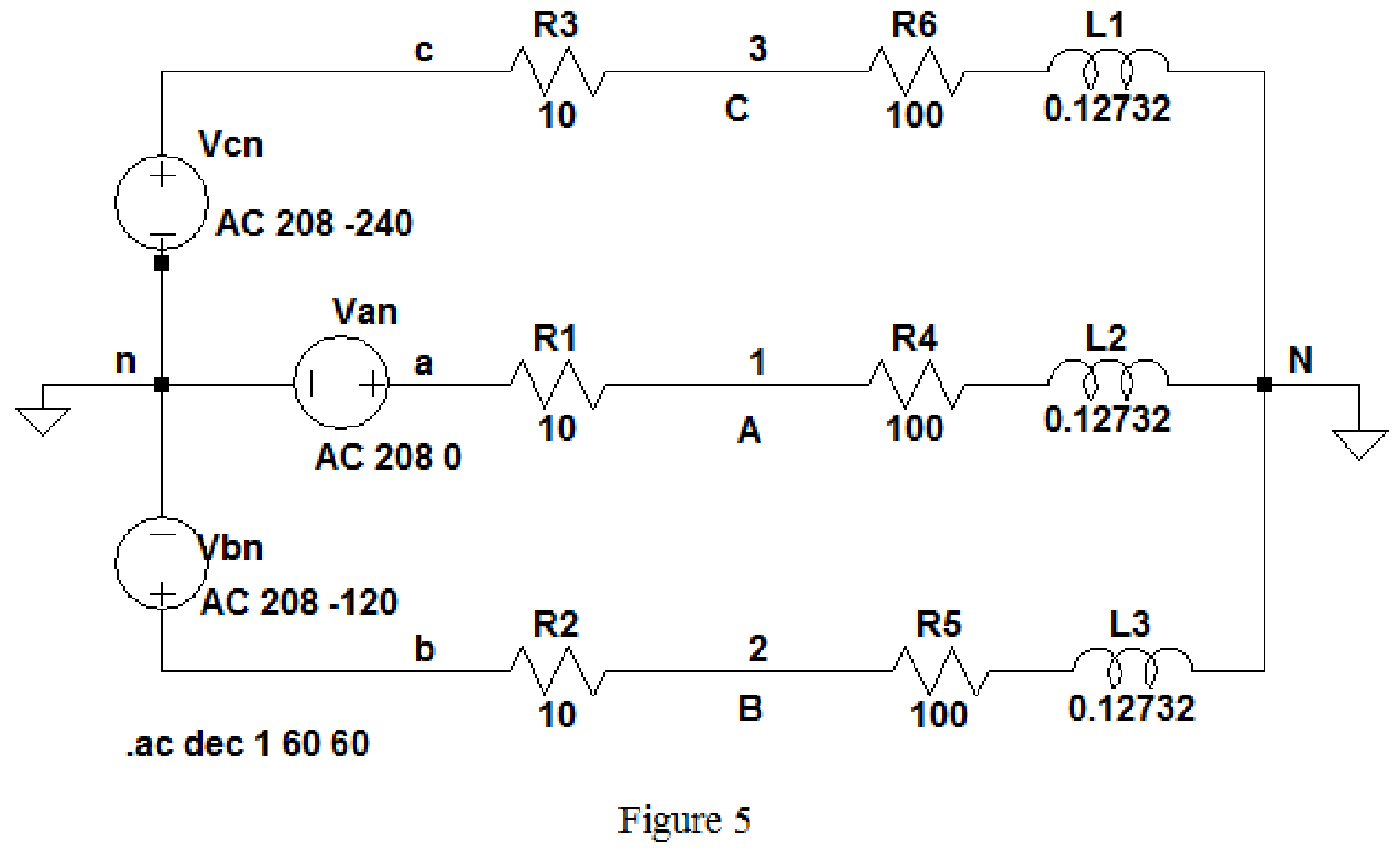
Keep the same simulation settings as given in Part(a) and run the simulation, then the output for the AC analysis will displays as shown in Figure 6.
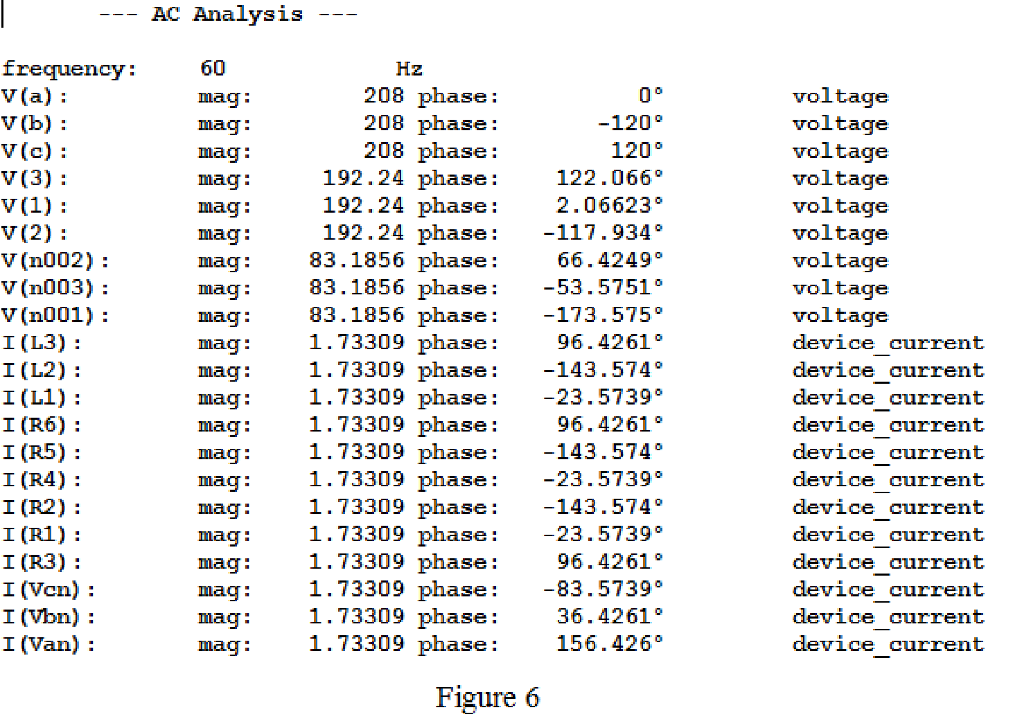
From above simulation results I(R1) or I(R4) or I(L1) is equals to
Then,
The phase voltages at the load
Then, the phase voltages at the load are,
The magnitude of the phase voltages is
Write the formula to find the line voltage
Substitute
Write the formula to find the line voltage
Substitute
Write the formula to find the line voltage
Substitute
Conclusion:
Thus, the line and phase currents are
The phase voltages are
(c)
Find the line and phase currents, line and phase voltages at the load when the load impedance
Answer to Problem 18E
The line and phase currents are
The phase voltages are
Explanation of Solution
Given data:
Refer to part (a).
LTspice Simulation:
The load impedance is given as,
Where load resistance is
Write the formula to find the inductive reactance as follows.
Substitute
Draw the given circuit diagram as shown in Figure 5 for the load impedance
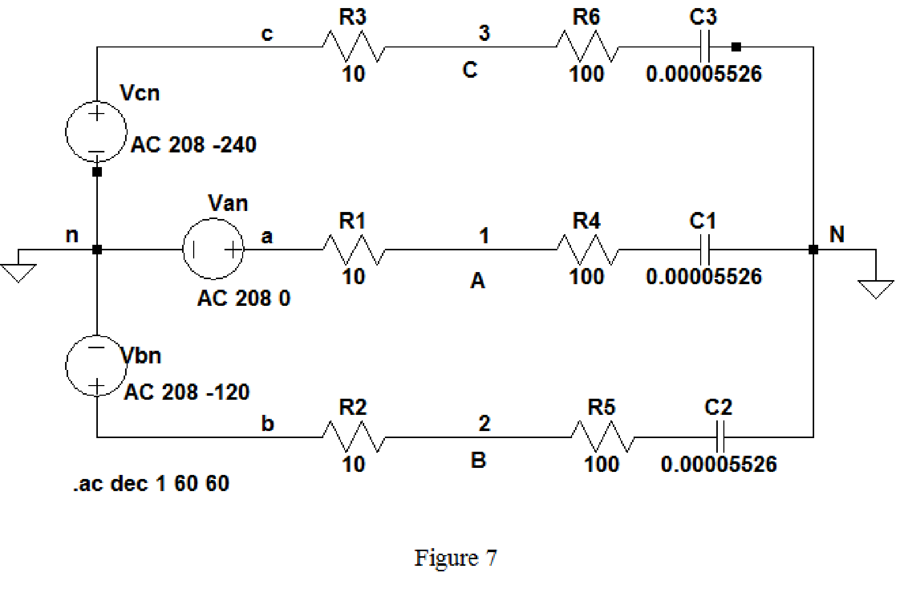
Keep the same simulation settings as given in part(a) and run the simulation, then the output for the AC analysis will displays as shown in Figure 8.
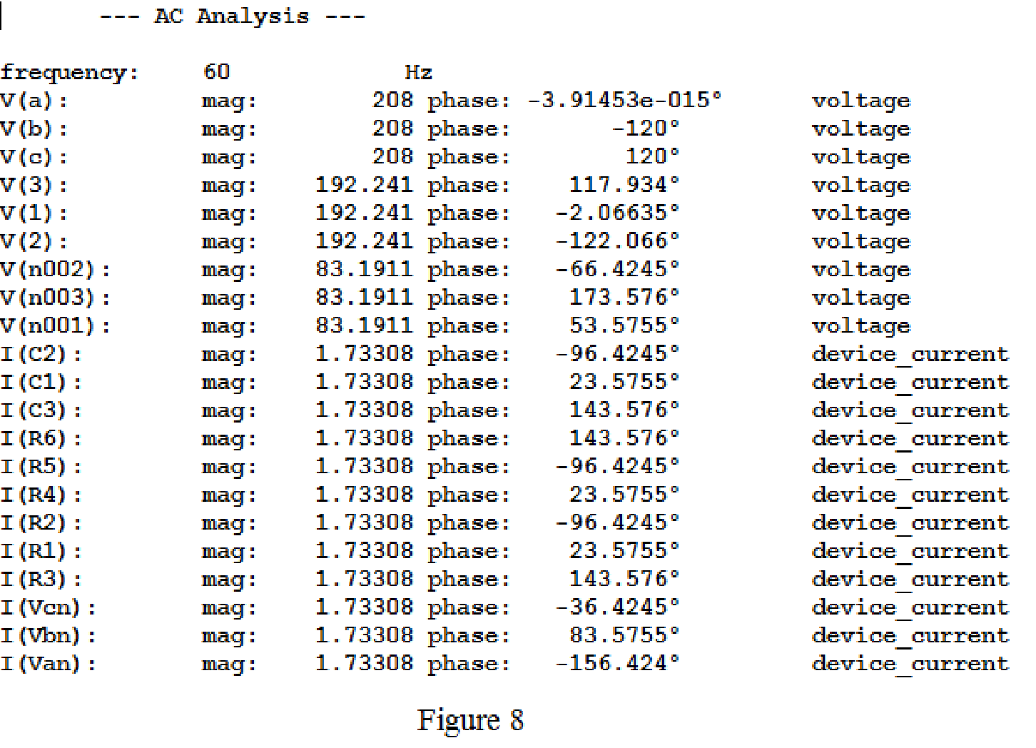
From above simulation results, since the phase currents and line currents are equal, I(R1) or I(R4) or I(C1) is equals to
Then,
The phase voltages at the load
Then, the phase voltages at the load are,
Use the same formula given in equation (1) to find the line voltage
Use the same formula given in equation (2) to find the line voltage
Use the same formula given in equation (3) to find the line voltage
Conclusion:
Thus, the line and phase currents are
The phase voltages are
Want to see more full solutions like this?
Chapter 12 Solutions
Loose Leaf for Engineering Circuit Analysis Format: Loose-leaf


- Consider the following power system model with the following entities:i. A generator generates a sinusoidal waveform with amplitude of 300 V and angular frequency of 5 radians,ii. The transmission line has a resistance of 1Ω, andiii. A capacitive load with a value of 2F presents at the end of the system. Answer the following questions:(a) Draw the relevant diagram and label all entity values of the power system as described above.(b) Replacing the real source in Figure from part (a) with a complex source, find the response of the steady-state capacitor voltage in time-domain.(c) Repeat the sub-question (a) above, now showing calculations in frequency-domain.(d) Repeat the sub-question (a) above, now showing calculations in s-domain.arrow_forwardConsider the following power system model with the following entities:i. A generator generates a sinusoidal waveform with amplitude of 300 V and angular frequency of 5 radians,ii. The transmission line has a resistance of 1Ω, andiii. A capacitive load with a value of 2F presents at the end of the system. Answer the following questions:(a) Draw the relevant diagram and label all entity values of the power system as described above.(b) Replacing the real source in Figure from part (a) with a complex source, find the response of the steady-state capacitor voltage in time-domain.(d) Repeat the sub-question (a) above, now showing calculations in s-domain.arrow_forwardКА CE3 Khalid Abdulrahman Abdullah Alqasmi O Search 05 Symm. B Share O Comme Slide Show Review View Help Design Transitions Animations 1. A 3- phase, 30 MVA, 33 KV alternator has internal reactance of 4% and negligible resistance. Find the external reactance per phase to be connected in series with the alternator so that steady current on short circuit does not exceed 10 times the full load. Also find Find the full load current. k to add poterarrow_forward
- Paragraph Styles Editing Voice Sensitvity Ed A balanced load connected to a three-phase supply comprises three identical coils in star. The line current is 25Amps.KVA input is 20 and KW input is 11.Find KVAR input, Phase voltage, line voltage ,resistance and reactance of each coil of the load. DFocus ted Statesarrow_forwardPlease answer quickly "In series-connected ac circuit, the total voltage across the circuit is always equal to the sum of the magnitude (only) of the individual voltage across each element." True False The power factor is equal to cosine of the phase difference. True False A leading power factor means that the circuit is predominantly capacitive in nature. True False "Since most loads are resistive in nature (e.g. motors), improvement of power factor is done by connecting capacitor banks or a synchronous condenser " True Falsearrow_forwardThree Impedances each of (12 -j18)N are connected in mesh across a three-phase 420V ac supply. Determine the phase current, line current, active power, reactive power drawn from the supply. phase current (Ip) Line current real power reactive powerarrow_forward
- For the circuit shown in Fig Q2, determine: (a) The total impedance seen by the source. (b) The total supply current (1) (c) The voltage across the capacitors (Ve) (d) The active power, reactive power and power factor of the source. R₁5602 E = 100V 200 560 + fr = 400 R₂200 + Ve Fig. Q2 Xc₁ = 400arrow_forwardFor the circuit shown in Fig. below , find a) the phase currents IAB, IBC, and IcCA b) the line currents IA, Ib, and Içc when Z1 = 2.4 - j0.7 N, Z = 8 + j6 N, and Z3 = 20 + j0 N. %3D 480/-120° V 480/0° V Zz В 480/120° Varrow_forwardHomework problem: The per-phase equivalent circuit parameters of a 400 V, 33 kW, 60 Hz, star-connected, 4 pole, 1755 rpm 3-0 IM are: R1= 0.2 N, X1= j0.5 2, Xm= j20 2, R2 = 0.12, X2 = 0.2 N. If the mechanical losses (windage and friction) are 650 W and iron losses are 300 W, determine the following when the motor operates at full load at rated speed: (a) The synchronous speed. (b) The slip. (c) The input current and power factor. (d) The input power. (e) The useful mechanical power. (f) The output torque. (g) The motor efficiency. Use exact equivalent circuit and simplified equivalent circuit and give comments on the results obtained.arrow_forward
- A star connected 3-phase alternator gives the following test result Open circuit Test: open circuit voltage, Eo (line to line) = 400V, at I = 2 A Short circuit Test: Short circuit current, Isc (line) = 10 A, at I = 2 A Find per phase synchronous impedance (Zs) O 23 Ohm O 20 Ohm O40 Ohm O 34.72 Ohmarrow_forward12.25 In the circuit of Fig. 12.54, if Vab = 220/10°, Vc = 220/-110°, Vca = 220/130° V, find the line ps currents. %3D %3D 3+j20 I a Vab 10 - j8 2 3+j20 I 10 – j8 2 10 - j8 2 3+j20 Iarrow_forwardThree coils connected in series across a 100 V, 50 Hz supply have the followingparameters:R1 = 18 Ω, L1 = 0.012 H; R2 = 12 Ω, L2 = 0.036 H; R3 = 3.6 Ω, L3 = 0.072 HDetermine the potential drop and phase angle for each coil. USE SERIES AC CIRCUITS METHOD NOT KIRCHOFF LAWS. PLS SHOW COMPLETE SOLUTION AND ROUND OFF TO FOUR DECIMAL PLACES , WRITE LEGIBLY PLS INLUDE ALSO THE CIRCUIT DIAGRAM:arrow_forward
 Introductory Circuit Analysis (13th Edition)Electrical EngineeringISBN:9780133923605Author:Robert L. BoylestadPublisher:PEARSON
 Delmar's Standard Textbook Of ElectricityElectrical EngineeringISBN:9781337900348Author:Stephen L. HermanPublisher:Cengage Learning
 Programmable Logic ControllersElectrical EngineeringISBN:9780073373843Author:Frank D. PetruzellaPublisher:McGraw-Hill Education
 Fundamentals of Electric CircuitsElectrical EngineeringISBN:9780078028229Author:Charles K Alexander, Matthew SadikuPublisher:McGraw-Hill Education
 Electric Circuits. (11th Edition)Electrical EngineeringISBN:9780134746968Author:James W. Nilsson, Susan RiedelPublisher:PEARSON
 Engineering ElectromagneticsElectrical EngineeringISBN:9780078028151Author:Hayt, William H. (william Hart), Jr, BUCK, John A.Publisher:Mcgraw-hill Education,