
Loose Leaf for Engineering Circuit Analysis Format: Loose-leaf
9th Edition
ISBN: 9781259989452
Author: Hayt
Publisher: Mcgraw Hill Publishers
expand_more
expand_more
format_list_bulleted
Concept explainers
Videos
Textbook Question
Chapter 12, Problem 37E
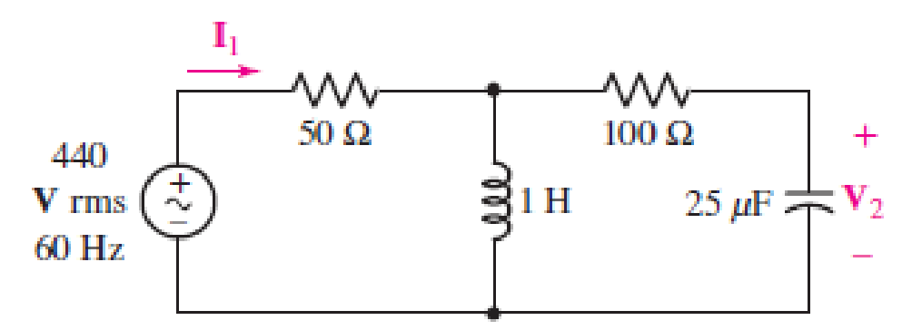
A wattmeter is connected into the circuit of Fig. 12.37 so that I1 enters the (+) terminal of the current coil, while V2 is the voltage across the potential coil. Find the wattmeter reading, and verify your solution with an appropriate simulation.
■ FIGURE 12.37
Expert Solution & Answer
Want to see the full answer?
Check out a sample textbook solution
Students have asked these similar questions
A circuit consist of a resistance of 30ohm in series with an inductance of 75mH, is connected in parallel with a circuit consisting a resistance of 20ohm in series with a capacitance of 100 micro farad. If parallel combination is connected with 240 volts . 50 cycle per second single phase supply. Calculate a). Current in each branch
b). Total current
C). Power factor
d). Total power consumed
A resistance of 20 ohm and a coil of inductance 31.8 mH and negligible resistance are connected in
parallel across 230V, 50 Hz supply. Find the
A) Line Current
B) Power Factor
C) Power consumed by the circuit
Ascertain the Actual values of the following given parameters 200mvA, 13.8kv generator which has a reactance of 0.85 pu and is generating 1.15pu voltage. a) Line voltage b) Phase voltage c) Reactance d)line and phase voltage with the new base of 500MVA, 13.5KV
Chapter 12 Solutions
Loose Leaf for Engineering Circuit Analysis Format: Loose-leaf
Ch. 12.1 - Let and . Find (a) Vad; (b) Vbc; (c) Vcd.Ch. 12.2 - Prob. 2PCh. 12.2 - Modify Fig. 12.9 by adding a 1.5 resistance to...Ch. 12.3 - A balanced three-phase three-wire system has a...Ch. 12.3 - A balanced three-phase three-wire system has a...Ch. 12.3 - Three balanced Y-connected loads are installed on...Ch. 12.4 - Each phase of a balanced three-phase -connected...Ch. 12.4 - Prob. 8PCh. 12.5 - Determine the wattmeter reading in Fig. 12.24,...Ch. 12.5 - Prob. 10P
Ch. 12 - Prob. 1ECh. 12 - Prob. 2ECh. 12 - Prob. 3ECh. 12 - Describe what is meant by a polyphase source,...Ch. 12 - Prob. 5ECh. 12 - Prob. 6ECh. 12 - Prob. 7ECh. 12 - Prob. 8ECh. 12 - Prob. 9ECh. 12 - Prob. 10ECh. 12 - The single-phase three-wire system of Fig. 12.31...Ch. 12 - Prob. 12ECh. 12 - Referring to the balanced load represented in Fig....Ch. 12 - Prob. 14ECh. 12 - Prob. 15ECh. 12 - Consider a simple positive phase sequence,...Ch. 12 - Assume the system shown in Fig. 12.34 is balanced,...Ch. 12 - Repeat Exercise 17 with Rw = 10 , and verify your...Ch. 12 - Prob. 19ECh. 12 - Prob. 20ECh. 12 - Prob. 21ECh. 12 - Prob. 22ECh. 12 - A three-phase system is constructed from a...Ch. 12 - Prob. 24ECh. 12 - Each load in the circuit of Fig. 12.34 is composed...Ch. 12 - Prob. 26ECh. 12 - Prob. 27ECh. 12 - A three-phase load is to be powered by a...Ch. 12 - For the two situations described in Exercise 28,...Ch. 12 - Prob. 30ECh. 12 - Prob. 31ECh. 12 - Prob. 32ECh. 12 - Repeat Exercise 32 if Rw = 1 . Verify your...Ch. 12 - Prob. 34ECh. 12 - Prob. 35ECh. 12 - Prob. 36ECh. 12 - A wattmeter is connected into the circuit of Fig....Ch. 12 - Find the reading of the wattmeter connected in the...Ch. 12 - (a) Find both wattmeter readings in Fig. 12.39 if...Ch. 12 - Circuit values for Fig. 12.40 are , , , , . Find...Ch. 12 - Prob. 41ECh. 12 - Prob. 42ECh. 12 - (a) Is the load represented in Fig. 12.41...Ch. 12 - Prob. 44E
Knowledge Booster


Learn more about
Need a deep-dive on the concept behind this application? Look no further. Learn more about this topic, electrical-engineering and related others by exploring similar questions and additional content below.Similar questions
- A parallel circuit consists of two branches. Branch A consists of R of 100 ohms connectedwith inductance of 1 H and branch B consists of R of 50 ohms in series with capacitanceof 79.5 micro Farad. This parallel circuit is connected across single phase 200 V, 50 Hzsupply, calculate:a. Branch currentsb. Total current drawn by the circuitc. Total power drawn by the circuitd. Total power factor of the circuitarrow_forwardImpedance, inductance, and reactance are all measured using ohms. a) True b) Falsearrow_forward2) A 240 Volt 60cycle source is connected to a coil of wire that has a resistance of 750 and an inductance of 0.0477 Henry. Calculate the following. a)impedance b)current c)power d) power factorarrow_forward
- generator (b) What is the average power dissipated in R? P=[ W Help Enter 500 v generator voltage -500 v AC Generator 0 Ideal Transformer R = 300 Rg8 time (a) The sinusoidal voltage output from the AC generator oscillates between 500 V and -500 V. The circuit for an ideal transformer is constructed with a generator, transformer and a 30 W resistor. The generator makes 6 loops with the transformer and the resistor makes 11 loops with the transformer (the figure does not show these loops accurately). What is the maximum voltage across the resistor R? V= V Help Enterarrow_forwardA 50 KVA, 2400:240 V, 60 Hz transformer has the following winding impedances H.V. side: 0.72+ j0.92 L.V. side: 0.007 + j0.009 2 Magnetising admittance, Y₁ = // = (0.324-j2.24)x102, referred to secondary (LV side) Zc Draw the equivalent circuit referring all parameters to H.V. & L.V. sides, respective/y,arrow_forwardConsider a RLC circuit shown in figure 2 below in which resistor, inductor and capacitor are connected in series across a Vmax 170V power supply having w = 750rad/sec. Detemine the following; R = 400 2 L 1.0 H C=4.0µF 170 Varrow_forward
- Figure 3 shows a transformers consists of soft-iron core, coils X and Y. [I Soft iron core aс, 240 V Coil X Coil Y Figure 3 When a 240 V power supply supplies current which change direction 100 times per second to the current X. Current is detected in coil Y, Describe above situation according to the physics understanding. Now, the output of coil Y is connected to a 12 V, 3 A light bulb. The bulb, light with full intensity. By using the concept of energy and assuming 100% energy efficiency between the two coils, calculate the current in coil X.arrow_forwardQ1.. no handwritten....find the value of admittance Y on given circuit diagramarrow_forwardA man has a body resistance of 600 . How much current flows through his ungrounded body: (a) when he touches the terminals of a 12-V autobattery? (b) when he sticks his finger into a 120-V light socket?arrow_forward
- tlineGet 24/7 homework help and experts with bartleby learn. Subscribe now!arrow_forward Question A circuit consist of a resistance of 30ohm in series with an inductance of 75mH, is connected in parallel with a circuit consisting a resistance of 20ohm in series with a capacitance of 100 micro farad. If parallel combination is connected with 240 volts . 50 cycle per second single phase supply. Calculate a). Current in each branch b). Total current C). Power factor d). Total power consumedarrow_forwardAn impedance coil is connected in series with a fixed resistor, and a 120-V, 50-cyclesource is then impressed across the combination. If the voltage drops across the coil andthe fixed resistor are 70 and 80 V, respectively, when the circuit current is 1.4 A, calculatethe resistance and inductance of the impedance coil. PLEASE ANSWER ASAParrow_forwardIn three phase power measurement using one watt-meter method, if the load is unbalanced then the total power is equal to P = W,+ W2. Select one: O True O False The open circuit voltage of a transformer is 246 V and its % regulation is 2.5 %, then the value of full load secondary voltage isarrow_forward
arrow_back_ios
SEE MORE QUESTIONS
arrow_forward_ios
Recommended textbooks for you

How do Electric Transmission Lines Work?; Author: Practical Engineering;https://www.youtube.com/watch?v=qjY31x0m3d8;License: Standard Youtube License