
Loose Leaf for Engineering Circuit Analysis Format: Loose-leaf
9th Edition
ISBN: 9781259989452
Author: Hayt
Publisher: Mcgraw Hill Publishers
expand_more
expand_more
format_list_bulleted
Concept explainers
Videos
Textbook Question
Chapter 12, Problem 25E
Each load in the circuit of Fig. 12.34 is composed of a 1.5 H inductor in parallel with a 100 μF capacitor and a 1 kΩ resistor. The resistance is labeled Rw = 0 Ω. Using positive phase sequence with Vab = 115∠0 ° Vat f = 60 Hz, determine the rms line current and the total power delivered to the load. Verify your answers with an appropriate simulation.
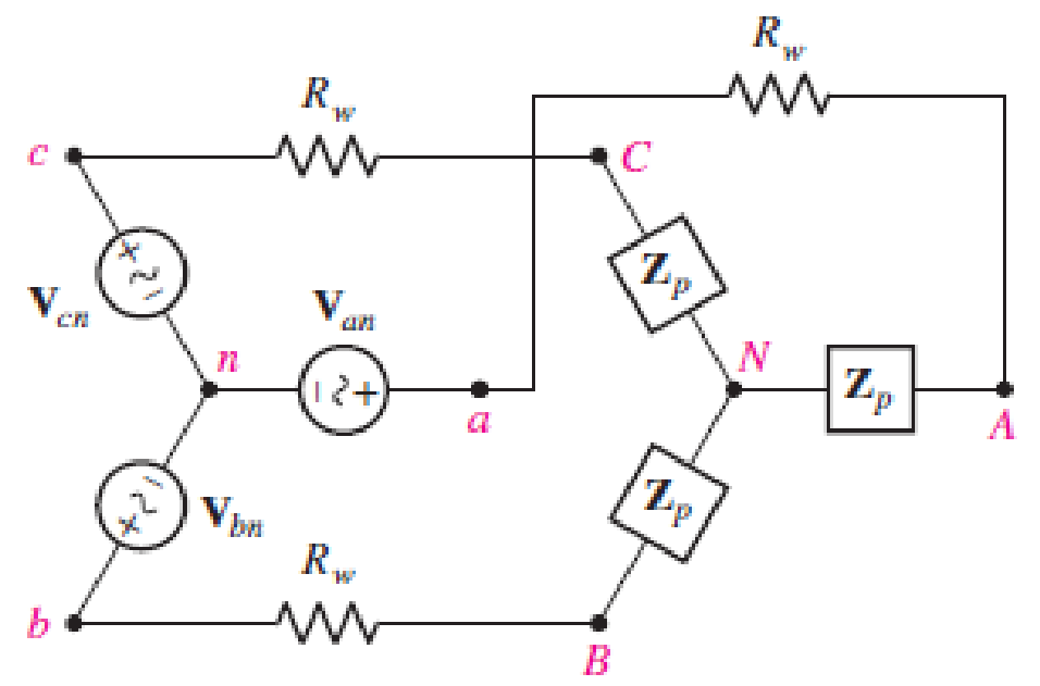
■ FIGURE 12.34
Expert Solution & Answer
Want to see the full answer?
Check out a sample textbook solution
Students have asked these similar questions
The currents in each branch of a two-branched parallel circuit are given by the expression
1₁ = 7.07 sin(314t - 4) and 2 = 21.2 sin(314t-3). The supply voltage is given by the
expression v = 354 sin 314t. Derive a similar expression for the supply current and calculate
the ohmic value of the component, assuming two pure component in each branch. State
whether the reactive components are inductive or capacitive.
In a R-C parallel circuit, total current is out of phase with the applied voltage."
True
False
In a R-C parallel circuit, total current is out of phase with the applied voltage."
True
False
In parallel-connected ac circuit, the value of the equivalent admittance of the circuit is equal to the phasor sum of the reciprocal of the individual admittances. "
True
False
Three coils connected in series across a 100 V, 50 Hz supply have the followingparameters:R1 = 18 Ω, L1 = 0.012 H; R2 = 12 Ω, L2 = 0.036 H; R3 = 3.6 Ω, L3 = 0.072 HDetermine the potential drop and phase angle for each coil.
USE SERIES AC CIRCUITS METHOD NOT KIRCHOFF LAWS.
PLS SHOW COMPLETE SOLUTION AND ROUND OFF TO FOUR DECIMAL PLACES , WRITE LEGIBLY
PLS INLUDE ALSO THE CIRCUIT DIAGRAM:
Chapter 12 Solutions
Loose Leaf for Engineering Circuit Analysis Format: Loose-leaf
Ch. 12.1 - Let and . Find (a) Vad; (b) Vbc; (c) Vcd.Ch. 12.2 - Prob. 2PCh. 12.2 - Modify Fig. 12.9 by adding a 1.5 resistance to...Ch. 12.3 - A balanced three-phase three-wire system has a...Ch. 12.3 - A balanced three-phase three-wire system has a...Ch. 12.3 - Three balanced Y-connected loads are installed on...Ch. 12.4 - Each phase of a balanced three-phase -connected...Ch. 12.4 - Prob. 8PCh. 12.5 - Determine the wattmeter reading in Fig. 12.24,...Ch. 12.5 - Prob. 10P
Ch. 12 - Prob. 1ECh. 12 - Prob. 2ECh. 12 - Prob. 3ECh. 12 - Describe what is meant by a polyphase source,...Ch. 12 - Prob. 5ECh. 12 - Prob. 6ECh. 12 - Prob. 7ECh. 12 - Prob. 8ECh. 12 - Prob. 9ECh. 12 - Prob. 10ECh. 12 - The single-phase three-wire system of Fig. 12.31...Ch. 12 - Prob. 12ECh. 12 - Referring to the balanced load represented in Fig....Ch. 12 - Prob. 14ECh. 12 - Prob. 15ECh. 12 - Consider a simple positive phase sequence,...Ch. 12 - Assume the system shown in Fig. 12.34 is balanced,...Ch. 12 - Repeat Exercise 17 with Rw = 10 , and verify your...Ch. 12 - Prob. 19ECh. 12 - Prob. 20ECh. 12 - Prob. 21ECh. 12 - Prob. 22ECh. 12 - A three-phase system is constructed from a...Ch. 12 - Prob. 24ECh. 12 - Each load in the circuit of Fig. 12.34 is composed...Ch. 12 - Prob. 26ECh. 12 - Prob. 27ECh. 12 - A three-phase load is to be powered by a...Ch. 12 - For the two situations described in Exercise 28,...Ch. 12 - Prob. 30ECh. 12 - Prob. 31ECh. 12 - Prob. 32ECh. 12 - Repeat Exercise 32 if Rw = 1 . Verify your...Ch. 12 - Prob. 34ECh. 12 - Prob. 35ECh. 12 - Prob. 36ECh. 12 - A wattmeter is connected into the circuit of Fig....Ch. 12 - Find the reading of the wattmeter connected in the...Ch. 12 - (a) Find both wattmeter readings in Fig. 12.39 if...Ch. 12 - Circuit values for Fig. 12.40 are , , , , . Find...Ch. 12 - Prob. 41ECh. 12 - Prob. 42ECh. 12 - (a) Is the load represented in Fig. 12.41...Ch. 12 - Prob. 44E
Knowledge Booster


Learn more about
Need a deep-dive on the concept behind this application? Look no further. Learn more about this topic, electrical-engineering and related others by exploring similar questions and additional content below.Similar questions
- A 60Hz, single-phase source with V=27730 volts is applied to a circuit element. (a) Determine the instantaneous source voltage. Also determine the phasor and instantaneous currents entering the positive terminal if the circuit element is (b) a 20 resistor. (C) a 10mH inductor, and (d) a capacitor with 25 reactance.arrow_forwardTransform 4A to independent voltage source and then determine the voltage drop at 2ohmsarrow_forward5. An impedance coil is connected in parallel with a capacitance C of 12.5 μF. The inputvoltage to the circuit is 100 V at 31.8 Hz. The phase angle between the two branchcurrents (I1 and I2) is 120° and the current in the first branch is I1 = 0.5A. Determine thefollowing:a) the current I2 and total currentb) the value of R and XLc) the value of inductor (L in mH)d) the total impedancee) the power factorf) the value of conductance (G in mƱ) and susceptance (B in Ʊ)g) total admittancearrow_forward
- An impedance coil is connected in parallel with a capacitance C of 12.5 μF. The input voltage to the circuit is 100 V at 31.8 Hz. The phase angle between the two branch currents (I1 and I2) is 120° and the current in the first branch is I1 = 0.5A. Determine the following:a) the current I2 and total currentb) the value of R and XLc) the value of inductor (L in mH)d) the total impedancee) the power factorf) the value of conductance (G in mƱ) and susceptance (B in Ʊ)g) total admittancearrow_forwardAn impedance coil is connected in parallel with a capacitance C of 12.5 μF. The input voltage to the circuit is 100 V at 31.8 Hz. The phase angle between the two branch currents (I1 and I2) is 120° and the current in the first branch is I1 = 0.5A. Determine the following:a) the power factorb) the value of conductance (G in mƱ) and susceptance (B in Ʊ)c) total admittancearrow_forwardA circuit is composed of a resistance of 22 ohms, an inductance of 0.11 henry and a capacitance of 12 microfarad, all connected in parallel to a 115-volt 60-Hz supply. Calculate the (a) total current, (b) total reactive power, (c) and the power factor of the cicruit.arrow_forward
- Problem 2 For the system shown in Figure 12.5: a) Find Is. b) Find the average power delivered to each element. c) Find the reactive power associated with each element. d) Find PT, QT, and ST. e) Find the power factor seen by the source E. R₁ ww 392 + E = 50 V/60° R3 ww 492 R₂ 12 Ω Χ 16Ω Xc 802 Figure 12.5arrow_forward9293 Conductance is always expressed as a imaginary number and comprised the imaginary part of admittance equation. True O False The admittance (Y) of a circuit is the sum of the phasor current to the phasor voltage. O True O Falsearrow_forwardThe impedance Z1 = 6+j8, Z2 = 8 -j6 and Z3 = 10+j0 ohms measured at 50Hz from three branches of a parallel circuit. This circuit is fed from a 100-volt 50-Hz supply. A purely reactive (inductive or capacitive) circuit is added as the fourth parallel branch to the above three-branched parallel circuit so as to draw minimum current from the source. Determine the value of L or C to be used in the fourth branch and also find the minimum current.arrow_forward
- An impedance coil is connected in parallel with a capacitance C of 12.5 μF. The input voltage to the circuit is 100 V at 31.8 Hz. The phase angle between the two branch currents (I1 and I2) is 120° and the current in the first branch is I1 = 0.5A. Determine the following: a.) the current I2 and total current (express answer in polar form) b.) the value of R and XL c.) the value of inductor (L in mH) d.) the total impedance (express answer in polar form) e.) the power factor f.) the value of conductance (G in mƱ) and susceptance (B in μƱ) g.) total admittance (express answer in polar form)arrow_forwardTwo impedances consist of resistance of (15 ohms and series connectedinductance of 0.04 henry) and (resistance of 10 ohms, inductance of 0.1 henryand a capacitance of 100 microfarad, all in series) are connected in series andare connected to 230 volts, 50 – Hz AC source. Find: (a) current drawn, (b) voltageacross each impedance, (c) individual and total power factor. Draw the phasordiagram.arrow_forward16 An alternating voltage v = 250 sin 800 t volts is applied across a series circuit containing a 30 2 resistor and 50 µF capacitor. Calcu- late (a) the circuit impedance, (b) the current flowing, (c) the p.d. across the resistor, (d) the p.d. across the capacitor, and (e) the phase angle between voltage and current [(a) 39.05 2 (b) 4.527 A (c) 135.8 V (d) 113.2 V (e) 39°48']arrow_forward
arrow_back_ios
SEE MORE QUESTIONS
arrow_forward_ios
Recommended textbooks for you
 Power System Analysis and Design (MindTap Course ...Electrical EngineeringISBN:9781305632134Author:J. Duncan Glover, Thomas Overbye, Mulukutla S. SarmaPublisher:Cengage Learning
Power System Analysis and Design (MindTap Course ...
Electrical Engineering
ISBN:9781305632134
Author:J. Duncan Glover, Thomas Overbye, Mulukutla S. Sarma
Publisher:Cengage Learning
Maximum Power Transfer Theorem Using Nodal Analysis & Thevenin Equivalent Circuits; Author: The Organic Chemistry Tutor;https://www.youtube.com/watch?v=8CA6ZNXgI-Y;License: Standard Youtube License