
Loose Leaf for Engineering Circuit Analysis Format: Loose-leaf
9th Edition
ISBN: 9781259989452
Author: Hayt
Publisher: Mcgraw Hill Publishers
expand_more
expand_more
format_list_bulleted
Concept explainers
Videos
Textbook Question
Chapter 12, Problem 43E
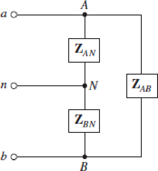
(a) Is the load represented in Fig. 12.41 considered a three-phase load? Explain. (b) If ZAN = 1 − j7 Ω,  and ZAB = 2 + j Ω, calculate all phase (and line) currents and voltages assuming a phase to neutral voltage of 120 VAC (the two phases are 180° out of phase). (c) Under what circumstances does current flow in the neutral wire?
FIGURE 12.41
Expert Solution & Answer
Want to see the full answer?
Check out a sample textbook solution
Students have asked these similar questions
1. What is the main direct cause of reactive power in AC system?
A. Resistance of transmission lines
B. Inductance and capacitance in the loads
C. Ideal transformer connected in the system
D. Power produced by generator
2. "Reactive power in a system is dissipated generally as thermal energy?"
A. TRUE
B. FALSE
3. Which of the following statements are correct for three phase circuit:
A. Sum of all the three phase currents is zero in unbalanced network
B. Total power transfer to load is constant with time
C. Neutral conductor is same size in terms of material used as in single phase conductors
D. Net apparent power consumed is equal to real power
current - 1=?, and the power factor - cosp =?.
4.
An out of balance three phase star connected load has the following complex currents:
I₁ = lejº,A, I₂ =le¯6⁰,A and I₁=1e¹j6⁰, A. This load is supplied by a four wire
power line from a balance voltage source. Find the r.m.s. value of the neutral current Io =?
Wait
to th
Please answer quickly
"In series-connected ac circuit, the total voltage across the circuit is always equal to the sum of the magnitude (only) of the individual voltage across each element."
True
False
The power factor is equal to cosine of the phase difference.
True
False
A leading power factor means that the circuit is predominantly capacitive in nature.
True
False
"Since most loads are resistive in nature (e.g. motors), improvement of power factor is done by connecting capacitor banks or a synchronous condenser "
True
False
Chapter 12 Solutions
Loose Leaf for Engineering Circuit Analysis Format: Loose-leaf
Ch. 12.1 - Let and . Find (a) Vad; (b) Vbc; (c) Vcd.Ch. 12.2 - Prob. 2PCh. 12.2 - Modify Fig. 12.9 by adding a 1.5 resistance to...Ch. 12.3 - A balanced three-phase three-wire system has a...Ch. 12.3 - A balanced three-phase three-wire system has a...Ch. 12.3 - Three balanced Y-connected loads are installed on...Ch. 12.4 - Each phase of a balanced three-phase -connected...Ch. 12.4 - Prob. 8PCh. 12.5 - Determine the wattmeter reading in Fig. 12.24,...Ch. 12.5 - Prob. 10P
Ch. 12 - Prob. 1ECh. 12 - Prob. 2ECh. 12 - Prob. 3ECh. 12 - Describe what is meant by a polyphase source,...Ch. 12 - Prob. 5ECh. 12 - Prob. 6ECh. 12 - Prob. 7ECh. 12 - Prob. 8ECh. 12 - Prob. 9ECh. 12 - Prob. 10ECh. 12 - The single-phase three-wire system of Fig. 12.31...Ch. 12 - Prob. 12ECh. 12 - Referring to the balanced load represented in Fig....Ch. 12 - Prob. 14ECh. 12 - Prob. 15ECh. 12 - Consider a simple positive phase sequence,...Ch. 12 - Assume the system shown in Fig. 12.34 is balanced,...Ch. 12 - Repeat Exercise 17 with Rw = 10 , and verify your...Ch. 12 - Prob. 19ECh. 12 - Prob. 20ECh. 12 - Prob. 21ECh. 12 - Prob. 22ECh. 12 - A three-phase system is constructed from a...Ch. 12 - Prob. 24ECh. 12 - Each load in the circuit of Fig. 12.34 is composed...Ch. 12 - Prob. 26ECh. 12 - Prob. 27ECh. 12 - A three-phase load is to be powered by a...Ch. 12 - For the two situations described in Exercise 28,...Ch. 12 - Prob. 30ECh. 12 - Prob. 31ECh. 12 - Prob. 32ECh. 12 - Repeat Exercise 32 if Rw = 1 . Verify your...Ch. 12 - Prob. 34ECh. 12 - Prob. 35ECh. 12 - Prob. 36ECh. 12 - A wattmeter is connected into the circuit of Fig....Ch. 12 - Find the reading of the wattmeter connected in the...Ch. 12 - (a) Find both wattmeter readings in Fig. 12.39 if...Ch. 12 - Circuit values for Fig. 12.40 are , , , , . Find...Ch. 12 - Prob. 41ECh. 12 - Prob. 42ECh. 12 - (a) Is the load represented in Fig. 12.41...Ch. 12 - Prob. 44E
Knowledge Booster


Learn more about
Need a deep-dive on the concept behind this application? Look no further. Learn more about this topic, electrical-engineering and related others by exploring similar questions and additional content below.Similar questions
- 12:45 1 A docs.google.com Section 1 The open circuit test in a transformer is used to (2) iha measure .also, keep secondary . terminals Total loss , short circuit Winding loss, open circuit Core loss , open circuit Copper loss , short circuit C isaly čhäi The separately excited D.C generator when field resistance increased at no * .. load, which one is change Torque O Voltage generator O Speed generator O Load current blä 4 The shunt excited D.C motor when field * resistance increased not decreased increased change The torque will be The current field will be The speed will be The flux will be Lala: If sunply freguency of a transformer O Oarrow_forwardIn a 3-phase, 4-wire system, two phases have currents of 10 A and 6 A in lagging power factors of 0.80 and 0.60, while the third phase is open circuited. Find the current in the neutral.arrow_forward13. In parallel-connected ac circuit, the total current though the circuit is always equal to the phasor sum of the individual current though each element. True False 14. In a R-C parallel circuit, R=10 ohms and Xc=10 ohms, the applied voltage is leading to the circuit total current by 45 degrees (assumed applied voltage is the reference). True False 15. In a R-C series circuit, applied voltage is in phase with the total current. True Falsearrow_forward
- 5. The figure below shows two star connected loads with three phase power. The voltage source is 120Z0°. The loads are Z₁ = 10 + j4 № and Z₂ = 2 +j3 №. The cables are negligible. Calculate: a) the line and phase current. b) the real power from the source. c) the reactive power of the circuit. Is V N Z₁ Z₁ Z₁ Z₂ Z₂ N N Z₂arrow_forwardA generator is rated 100 MW, 13.8kV and 90% power factor. The effectiveresistance is 1.5 times the ohmic resistance. The ohmic resistance isobtained by connecting two terminals to a DC source. The current andvoltage are 87.6 A and 6 V respectively. What is the DC resistance perphase? What is the effective resistance per phase? Whole Solutionarrow_forwardProblem 1 For the system shown in Figure 12.9: a) Find PT, QT, and ST. b) Draw the power triangle. c) Find the power factor seen by the source E. d) Find Is. + E 120 V/50° Load 1 1100 VAR (C) 750 W Load 2 950 VAR (L) 100 W Load 4 700 VAR (C) 200 W Load 3 Figure 12.9 1900 VAR (L) 500 Warrow_forward
- Find the unknown currents in figure below: Assume X =20 A. Y =13 A Z =8 A YA 5A I: XA + ZA 3A 12. 14 31arrow_forwardConsider a 10 kVA, 200/400 V, 50 HZ: single-phase tranformer has the folloving test results:0.C. test: 200 V, 0.6A, 63 W (L.V.side)S.C. test : 20 V, 25A, 85 W (H.V. side)Deternine:i- The eficiengy at 75 % offiull-load at 0.9 leading power factor.ii -The secondary terminal voltage on fill-load at tunity power factonarrow_forwardChoose the correct answer: Capacitors in AC circuits dissipate power in the form of heat Select one: O True O False Choose the correct answer: In a balanced three-phase system, phase shift between phase and line voltage is 30". Select one: O True O False What is the phase shift between a phase current and its voltage in a three-phase balanced system? O a. 90 O b. It can be anything, it depends on system parameters. O C. 120 Od 30°arrow_forward
- Problem 2 For the system shown in Figure 12.5: a) Find Is. b) Find the average power delivered to each element. c) Find the reactive power associated with each element. d) Find PT, QT, and ST. e) Find the power factor seen by the source E. R₁ ww 392 + E = 50 V/60° R3 ww 492 R₂ 12 Ω Χ 16Ω Xc 802 Figure 12.5arrow_forwardThe values of the elements for the given circuit are given below.What is the maximum average power that can be transferred to the ZL load?R1 = 400 OhmsL = 500j OhmsR2 = 100 Ohmsarrow_forwardChatGPT 3.5 You A balanced load is connected in star across a 3 phase 415V 50Hz supply. The load consists of a coil of resistance 25 ohms and inductance 0.5 henry in parallel with a pure resistance of 28 ohms and a pure capacitor of 60 microfarads capacitance ib each branch Calculate I. The line currents Ii. The overall power factor. iii. The power delivered from the supply. iv. The power dissipated in the resistors and coils. v. The current in the neutral supported by a reason why its value is that deduced ?arrow_forward
arrow_back_ios
SEE MORE QUESTIONS
arrow_forward_ios
Recommended textbooks for you
 Power System Analysis and Design (MindTap Course ...Electrical EngineeringISBN:9781305632134Author:J. Duncan Glover, Thomas Overbye, Mulukutla S. SarmaPublisher:Cengage Learning
Power System Analysis and Design (MindTap Course ...
Electrical Engineering
ISBN:9781305632134
Author:J. Duncan Glover, Thomas Overbye, Mulukutla S. Sarma
Publisher:Cengage Learning
What is the Difference Between Single Phase and Three Phase???; Author: Electrician U;https://www.youtube.com/watch?v=FEydcr4wJw0;License: Standard Youtube License