
Loose Leaf for Engineering Circuit Analysis Format: Loose-leaf
9th Edition
ISBN: 9781259989452
Author: Hayt
Publisher: Mcgraw Hill Publishers
expand_more
expand_more
format_list_bulleted
Concept explainers
Videos
Textbook Question
Chapter 9, Problem 33E
Analyze the circuit described in Exercise 31 to find v(t), t > 0, if R is equal to (a) 2 kΩ; (b) 2 Ω. (c) Graph both responses over the range of 0 ≤ t ≤ 60 ms. (d) Verify your answers with appropriate SPICE simulations.
31. The source-free circuit depicted in Fig. 9.1 is constructed using a 10 mH inductor, a 1 mF capacitor, and a 1.5 kΩ resistor. (a) Calculate α, ωd, and ω0. (b) Write the equation which describes the current i for t > 0. (c) Determine the maximum value of i, and the time at which it occurs, if the inductor initially stores no energy and v(0−) = 9 V.
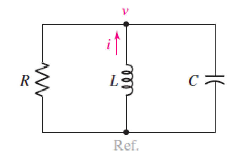
■ FIGURE 9.1 The source-free parallel RLC circuit.
Expert Solution & Answer
Want to see the full answer?
Check out a sample textbook solution
Students have asked these similar questions
The current in the circuit is known to bei=B1e−2000tcos1500t+B2e−2000tsin1500t, t≥0.The capacitor has a value of 80 nF; the initial value of the current is 7.5mA; and the initial voltage on the capacitor is –30 V. Find the values ofR, L, B1, and B2
The circuit shown contains two switches that always move in perfect synchronization. However, when switch A
opens, switch B closes, and vice versa. Swtich A is initially open, while B is initially closed; they change
pistions every 40 ms. Find the voltage across the capacitor when t= 40(+)ms.
Hint: Use the bottom node as a reference node.
3 A
10 mF :
10 N
9 A(
In the circuit shown, the switch indicated open for a very long time, and then closed at t=0. When the switch moves, there is a transient response in the inductor current (indicated on the
diagram as i). The component values are R1 = 1.1 k0, R2 = 2.2 k0, R3 = 2.2 kQ, L = 80 mH, C = 90 nF, Vs = 3 V.
VS
Q=
+
2
No.
20
1
R1 Ω
ww
+1₁
R2 Ω
+
m
V
t=
LH
m
Find the quality factor of the transient response (i.e. Q), to within 1% precision.
> Okok
Chapter 9 Solutions
Loose Leaf for Engineering Circuit Analysis Format: Loose-leaf
Ch. 9.1 - A parallel RLC circuit contains a 100 2 resistor...Ch. 9.2 - After being open for a long time, the switch in...Ch. 9.2 - Prob. 3PCh. 9.2 - Prob. 4PCh. 9.3 - (a) Choose R1 in the circuit of Fig. 9.14 so that...Ch. 9.4 - Prob. 6PCh. 9.5 - Prob. 7PCh. 9.5 - Prob. 8PCh. 9.6 - Let is = 10u(t) 20u(t) A in Fig. 9.31. Find (a)...Ch. 9.6 - Let vs = 10 + 20u(t) V in the circuit of Fig....
Ch. 9.7 - Alter the capacitor value and voltage source in...Ch. 9 - For a certain source-free parallel RLC circuit, R...Ch. 9 - Element values of 10 mF and 2 nH are employed in...Ch. 9 - If a parallel RLC circuit is constructed from...Ch. 9 - Prob. 4ECh. 9 - You go to construct the circuit in Exercise 1,...Ch. 9 - A parallel RLC circuit has inductance 2 mH and...Ch. 9 - Prob. 7ECh. 9 - A parallel RLC circuit has R = 1 k, L = 50 mH. and...Ch. 9 - Prob. 9ECh. 9 - Prob. 10ECh. 9 - The current flowing through a 5 resistor in a...Ch. 9 - For the circuit of Fig.9.40, obtain an expression...Ch. 9 - Consider the circuit depicted in Fig. 9.40. (a)...Ch. 9 - With regard to the circuit represented in Fig....Ch. 9 - (a) Assuming the passive sign convention, obtain...Ch. 9 - With regard to the circuit presented in Fig. 9.42,...Ch. 9 - Obtain expressions for the current i(t) and...Ch. 9 - FIGURE 9.43 Replace the 14 resistor in the...Ch. 9 - Design a complete source-free parallel RLC circuit...Ch. 9 - For the circuit represented by Fig. 9.44, the two...Ch. 9 - Prob. 21ECh. 9 - Prob. 22ECh. 9 - A critically damped parallel RLC circuit is...Ch. 9 - A source-free parallel RLC circuit has an initial...Ch. 9 - A critically damped parallel RLC circuit is...Ch. 9 - For the circuit of Fig. 9.45, is(t) = 30u(t) mA....Ch. 9 - Prob. 27ECh. 9 - The circuit of Fig. 9.44 is rebuilt such that the...Ch. 9 - Prob. 29ECh. 9 - Prob. 30ECh. 9 - The source-free circuit depicted in Fig. 9.1 is...Ch. 9 - (a) Graph the current i for the circuit described...Ch. 9 - Analyze the circuit described in Exercise 31 to...Ch. 9 - A source-free parallel RLC circuit has capacitance...Ch. 9 - Prob. 35ECh. 9 - Obtain an expression for vL(t), t 0, for the...Ch. 9 - For the circuit of Fig. 9.47, determine (a) the...Ch. 9 - (a) Design a parallel RLC circuit that provides a...Ch. 9 - The circuit depicted in Fig. 9.48 is just barely...Ch. 9 - When constructing the circuit of Fig. 9.48, you...Ch. 9 - The circuit of Fig. 9.22a is constructed with a...Ch. 9 - Prob. 42ECh. 9 - Prob. 43ECh. 9 - The simple three-element series RLC circuit of...Ch. 9 - Prob. 45ECh. 9 - Prob. 46ECh. 9 - Prob. 47ECh. 9 - With reference to the series RLC circuit of Fig....Ch. 9 - Obtain an expression for i1 as labeled in Fig....Ch. 9 - The circuit in Fig. 9.52 has the switch in...Ch. 9 - For the circuit in Fig. 9.52, determine the value...Ch. 9 - In the series circuit of Fig. 9.53, set R = 1 ....Ch. 9 - Evaluate the derivative of each current and...Ch. 9 - Consider the circuit depicted in Fig. 9.55. If...Ch. 9 - Prob. 55ECh. 9 - In the circuit shown in Fig. 9.56, (a) obtain an...Ch. 9 - Prob. 57ECh. 9 - For the circuit represented in Fig. 9.57, (a)...Ch. 9 - FIGURE 9.57 Replace the 1 resistor in Fig. 9.57...Ch. 9 - A circuit has an inductive load of 2 H, a...Ch. 9 - (a) Adjust the value of the 3 resistor in the...Ch. 9 - Determine expressions for vC(t) and iL(t) in Fig....Ch. 9 - The capacitor in the LC circuit in Fig. 9.60 has...Ch. 9 - Suppose that the switch in the circuit in Fig....Ch. 9 - The capacitor in the circuit of Fig. 9.63 is set...Ch. 9 - The physical behavior of automotive suspension...Ch. 9 - A lossless LC circuit can be used to provide...
Knowledge Booster


Learn more about
Need a deep-dive on the concept behind this application? Look no further. Learn more about this topic, electrical-engineering and related others by exploring similar questions and additional content below.Similar questions
- Consider the circuit shown, the initial current in the inductor is it (0-) = -0.2A. The switch, has been close for a long time prior to t=0. It opens at t=0. Find expressions for it (t) and v(t) for t≥ 0. Sketch i(t) and v(t) versus time. Write down your detailed calculations step by step and use your words to explain your approach. 0.3A t=0 охо + V(t) 10 mH 2 ΚΩ i₁(t)arrow_forwardDetermine the voltage across the capacitor vc(t) for t≥0. Given that V1 = 15V, R1 = 0.5kQ, R2 = 2kQ, and C = 0.4 F. r=0arrow_forwardConsider the given circuit. The switch has been closed for a very long time before opening at t=0s. Determine the expression for Io(t) for t≥0 (in ms) and the expression for the inductor voltage for t≥0.arrow_forward
- Consider the circuit. The switch has been closed for a long time before opening at t=0s. Give the expression for the capacitor current for t≥0 and the total dissipated energy (in μJ) in the 10KΩ resistor 5ms after the switch has been opened.arrow_forwardThe switch has been in position a for a long time. At t=0, the switch moves from position a to position b. The switch is a make-before-break type so there is no interruption of the inductor current. 292 www b a 24V (+ 200mH 1092 8A V a. Find the expression for i(t) for t≥ 0. b. What is the initial voltage across the inductor after the switch has been moved to position b? c. Does this initial voltage make sense in terms of circuit behavior? d. How many milliseconds after the switch has been put in position b does the inductor voltage equal 24V? e. Plot both i(t) and v(t) versus t.arrow_forwardThe circuit elements in the circuit L=50 mH, and C=0.2 μF. The initial inductor current is−45 mA and the initial capacitor voltage is 15 V. The resistance is increased to250 Ω. Find the expression for v(t) for t≥0.arrow_forward
- An LC circuit like that in the figure below consists of a 3.30-H inductor and an 830-pF capacitor that initially carries a 121-µC charge. The switch is open for t < 0 and is then thrown closed at t = 0. Compute the following quantities at t = 5.00 ms. C max S ele (a) the energy stored in the capacitor 1.73 X Your response differs from the correct answer by more than 100%. J (b) the total energy in the circuit 8.82 J (c) the energy stored in the inductor Jarrow_forwardThe current at the terminals of the two capacitors shown is 240e −10tμA for t≥0. The initial values of v1 and v2 are −10 V and −5 V, respectively. Calculate the total energy trapped in the capacitors as t→∞. (Hint: Don’t combine the capacitors in series—find the energy trapped in each, and then add.)arrow_forwardThe switch in the circuit has been open for a long time before closingat t = 0 s a) Draw the RC circuit for t < 0 and calculate the capacitor voltage just beforethe switching, Vc(0−). b) Draw the circuit after switch has closed (for t > 0), and obtain the Theveninequivalent as seen by the 5 nF capacitor. c) What is the voltage across the capacitor when t → ∞? d) Find the numerical expression for Vc(t) for t ≥ 0 s. e) Find the numerical expression for ic(t) for t ≥ 0 s. f)Find the numerical expression for the power delivered by the voltage controlled current source for t ≥ 0 s.arrow_forward
- 1. (a) Obtain the steady-state response of the following model, and estimate how long it will take the response to reach steady-state. 13i - 6x = 18u,(t), r(0) = 2 %3D (b) Obtain the response of the following model. # + 8* + 12x = 0, x(0) = 0, i(0) = 1 (c) Find the response for the following model. The initial conditions are zero. 3* + 21i + 30r = 4t %3Darrow_forwardThe RC circuit shown on the right consists of a 1 µF capacitance, with an initial stored energy of 450 µµJ and a lkN resistance. If the circuit is subjected to a dc forcing voltage Vs, and if it is found that v(2 ms) = 0 a) Find Vs b) How much voltage changes v(t = 0.1ms) to v(t=lms)arrow_forwardExercise 3) In the LRC circuit below, at time t = 0 the current in the inductor is io = 0.354 A. A voltage is applied to the circuit at time t = ti sec and held constant until t = t2 sec before it is turned off, as shown on the right. Consider R = 1 N, L = 2 H and C = 0.5 F. R L v(t)A 1 v(t) C ti t2 t We wish to determine the current through the circuit i(t) considering the applied voltage v(t) and the initial current in the inductor io using the Laplace transform. Follow the steps below. (a) Write the differential equation relating i(t) and v(t). At this time the values of t1 and t2 do not need to be specified. (b) Take the Laplace transform of (a) considering the initial current in the inductor. (c) Solve for the current using the inverse Laplace transform.arrow_forward
arrow_back_ios
SEE MORE QUESTIONS
arrow_forward_ios
Recommended textbooks for you
 Introductory Circuit Analysis (13th Edition)Electrical EngineeringISBN:9780133923605Author:Robert L. BoylestadPublisher:PEARSON
 Delmar's Standard Textbook Of ElectricityElectrical EngineeringISBN:9781337900348Author:Stephen L. HermanPublisher:Cengage Learning
 Programmable Logic ControllersElectrical EngineeringISBN:9780073373843Author:Frank D. PetruzellaPublisher:McGraw-Hill Education
 Fundamentals of Electric CircuitsElectrical EngineeringISBN:9780078028229Author:Charles K Alexander, Matthew SadikuPublisher:McGraw-Hill Education
 Electric Circuits. (11th Edition)Electrical EngineeringISBN:9780134746968Author:James W. Nilsson, Susan RiedelPublisher:PEARSON
 Engineering ElectromagneticsElectrical EngineeringISBN:9780078028151Author:Hayt, William H. (william Hart), Jr, BUCK, John A.Publisher:Mcgraw-hill Education,
Introductory Circuit Analysis (13th Edition)
Electrical Engineering
ISBN:9780133923605
Author:Robert L. Boylestad
Publisher:PEARSON
Delmar's Standard Textbook Of Electricity
Electrical Engineering
ISBN:9781337900348
Author:Stephen L. Herman
Publisher:Cengage Learning
Programmable Logic Controllers
Electrical Engineering
ISBN:9780073373843
Author:Frank D. Petruzella
Publisher:McGraw-Hill Education
Fundamentals of Electric Circuits
Electrical Engineering
ISBN:9780078028229
Author:Charles K Alexander, Matthew Sadiku
Publisher:McGraw-Hill Education
Electric Circuits. (11th Edition)
Electrical Engineering
ISBN:9780134746968
Author:James W. Nilsson, Susan Riedel
Publisher:PEARSON
Engineering Electromagnetics
Electrical Engineering
ISBN:9780078028151
Author:Hayt, William H. (william Hart), Jr, BUCK, John A.
Publisher:Mcgraw-hill Education,
ENA 9.2(1)(En)(Alex) Sinusoids & Phasors - Explanation with Example 9.1 ,9.2 & PP 9.2; Author: Electrical Engineering Academy;https://www.youtube.com/watch?v=vX_LLNl-ZpU;License: Standard YouTube License, CC-BY
Electrical Engineering: Ch 10 Alternating Voltages & Phasors (8 of 82) What is a Phasor?; Author: Michel van Biezen;https://www.youtube.com/watch?v=2I1tF3ixNg0;License: Standard Youtube License