
Loose Leaf for Engineering Circuit Analysis Format: Loose-leaf
9th Edition
ISBN: 9781259989452
Author: Hayt
Publisher: Mcgraw Hill Publishers
expand_more
expand_more
format_list_bulleted
Concept explainers
Videos
Textbook Question
Chapter 9, Problem 39E
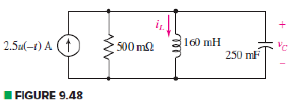
The circuit depicted in Fig. 9.48 is just barely underdamped. (a) Compute α and ωd. (b) Obtain an expression for iL(t) valid for t > 0. (c) Determine how much energy is stored in the capacitor, and in the inductor, at t = 200 ms.
Expert Solution & Answer
Want to see the full answer?
Check out a sample textbook solution
Students have asked these similar questions
Natural Response of RLC Circuita. charge in capacitor at steady state
b. di/dt (in A/s) at t=0+(The previous answer which were 0.001 and -31.25 were incorrect. I do not know what were the miscalculations, please do NOT provide those as answers anymore. Thanks)
In the figure below, the switch is open for a long time and the switch is closed at t = 0 .a) Find the initial conditions for t = 0? (Vc(0)=?,iL(0)=?)b) Find for the inductor current for t >=0 ?(iL(t)=?)c) Find the capacitor voltage and current through the switch (isw) for t >=0 ? (Vc(t)=?)
In the given circuit, consider M = 1 H.
Determine the energy stored in the coupled inductors at t = 2 s.
The energy stored in the coupled inductors is J
Chapter 9 Solutions
Loose Leaf for Engineering Circuit Analysis Format: Loose-leaf
Ch. 9.1 - A parallel RLC circuit contains a 100 2 resistor...Ch. 9.2 - After being open for a long time, the switch in...Ch. 9.2 - Prob. 3PCh. 9.2 - Prob. 4PCh. 9.3 - (a) Choose R1 in the circuit of Fig. 9.14 so that...Ch. 9.4 - Prob. 6PCh. 9.5 - Prob. 7PCh. 9.5 - Prob. 8PCh. 9.6 - Let is = 10u(t) 20u(t) A in Fig. 9.31. Find (a)...Ch. 9.6 - Let vs = 10 + 20u(t) V in the circuit of Fig....
Ch. 9.7 - Alter the capacitor value and voltage source in...Ch. 9 - For a certain source-free parallel RLC circuit, R...Ch. 9 - Element values of 10 mF and 2 nH are employed in...Ch. 9 - If a parallel RLC circuit is constructed from...Ch. 9 - Prob. 4ECh. 9 - You go to construct the circuit in Exercise 1,...Ch. 9 - A parallel RLC circuit has inductance 2 mH and...Ch. 9 - Prob. 7ECh. 9 - A parallel RLC circuit has R = 1 k, L = 50 mH. and...Ch. 9 - Prob. 9ECh. 9 - Prob. 10ECh. 9 - The current flowing through a 5 resistor in a...Ch. 9 - For the circuit of Fig.9.40, obtain an expression...Ch. 9 - Consider the circuit depicted in Fig. 9.40. (a)...Ch. 9 - With regard to the circuit represented in Fig....Ch. 9 - (a) Assuming the passive sign convention, obtain...Ch. 9 - With regard to the circuit presented in Fig. 9.42,...Ch. 9 - Obtain expressions for the current i(t) and...Ch. 9 - FIGURE 9.43 Replace the 14 resistor in the...Ch. 9 - Design a complete source-free parallel RLC circuit...Ch. 9 - For the circuit represented by Fig. 9.44, the two...Ch. 9 - Prob. 21ECh. 9 - Prob. 22ECh. 9 - A critically damped parallel RLC circuit is...Ch. 9 - A source-free parallel RLC circuit has an initial...Ch. 9 - A critically damped parallel RLC circuit is...Ch. 9 - For the circuit of Fig. 9.45, is(t) = 30u(t) mA....Ch. 9 - Prob. 27ECh. 9 - The circuit of Fig. 9.44 is rebuilt such that the...Ch. 9 - Prob. 29ECh. 9 - Prob. 30ECh. 9 - The source-free circuit depicted in Fig. 9.1 is...Ch. 9 - (a) Graph the current i for the circuit described...Ch. 9 - Analyze the circuit described in Exercise 31 to...Ch. 9 - A source-free parallel RLC circuit has capacitance...Ch. 9 - Prob. 35ECh. 9 - Obtain an expression for vL(t), t 0, for the...Ch. 9 - For the circuit of Fig. 9.47, determine (a) the...Ch. 9 - (a) Design a parallel RLC circuit that provides a...Ch. 9 - The circuit depicted in Fig. 9.48 is just barely...Ch. 9 - When constructing the circuit of Fig. 9.48, you...Ch. 9 - The circuit of Fig. 9.22a is constructed with a...Ch. 9 - Prob. 42ECh. 9 - Prob. 43ECh. 9 - The simple three-element series RLC circuit of...Ch. 9 - Prob. 45ECh. 9 - Prob. 46ECh. 9 - Prob. 47ECh. 9 - With reference to the series RLC circuit of Fig....Ch. 9 - Obtain an expression for i1 as labeled in Fig....Ch. 9 - The circuit in Fig. 9.52 has the switch in...Ch. 9 - For the circuit in Fig. 9.52, determine the value...Ch. 9 - In the series circuit of Fig. 9.53, set R = 1 ....Ch. 9 - Evaluate the derivative of each current and...Ch. 9 - Consider the circuit depicted in Fig. 9.55. If...Ch. 9 - Prob. 55ECh. 9 - In the circuit shown in Fig. 9.56, (a) obtain an...Ch. 9 - Prob. 57ECh. 9 - For the circuit represented in Fig. 9.57, (a)...Ch. 9 - FIGURE 9.57 Replace the 1 resistor in Fig. 9.57...Ch. 9 - A circuit has an inductive load of 2 H, a...Ch. 9 - (a) Adjust the value of the 3 resistor in the...Ch. 9 - Determine expressions for vC(t) and iL(t) in Fig....Ch. 9 - The capacitor in the LC circuit in Fig. 9.60 has...Ch. 9 - Suppose that the switch in the circuit in Fig....Ch. 9 - The capacitor in the circuit of Fig. 9.63 is set...Ch. 9 - The physical behavior of automotive suspension...Ch. 9 - A lossless LC circuit can be used to provide...
Knowledge Booster


Learn more about
Need a deep-dive on the concept behind this application? Look no further. Learn more about this topic, electrical-engineering and related others by exploring similar questions and additional content below.Similar questions
- An LC circuit like the one in the figure below contains an 75.0 mH inductor and a 30.0 µF capacitor that initially carries a 165 µC charge. The switch is open for t < 0 and is then thrown closed at t = 0. Qmax S (a) Find the frequency (in hertz) of the resulting oscillations. Hz (b) At t = 1.00 ms, find the charge on the capacitor. (c) At t = 1.00 ms, find the current in the circuit.arrow_forward4. Assume that at the instant the 2A DC current source is applied to the circuit shown below, the initialcurrent in the 39 mH inductor is 1A, and the initial voltage on the capacitor is 50 V (positive at theupper terminal). Find the expression for iL(t) for t ≥ 0 if R equals 12.5 ohms.arrow_forward3. If the switch changes position (from b-c to a-b) at t-0, find the capacitor voltage ve(t) for t20. Calculate the energy stored in the capacitor at t-10ms. y (12) 10 (2) 5 (1) 10y (V)( 2y (2) 5 (A) 5 (mF) vat)arrow_forward
- 9.pdf - Adobe Acrobat Reader DC (64-bit) ndow Help FINAL EP QP_SEM . x Sign In 10 / 12 116% Search Combine PDF Export PDF A capacitor is charged with 50 mC in a time of 20 uS. If the energy stored in the capacitor is 5 J, Edit PDF find (i) voltage across the capacitor, (ii) current through the capacitor and (iii) value of capacitance. Create PDF EComment Combine Files E0 Organize Pag Delete, insert, extract and rotate pages. Try now Convert, edit and e-sign Parrow_forwardIf in a circuit, E=9v and the current I reaches half its maximum value of 2A at t=0.1s after the switch is closed. What is the time constant of the circuit? What is the emf across the inductor at t=0.1s?arrow_forward4. The switch shown in Figure has been open for a long time before closing at t = 0. Write the expression for the capacitor voltage,v(t), for t 2 0arrow_forward
- In an oscillating LC circuit, the total stored energy is (6.11x10^-1) J and the maximum charge on the capacitor is (5.6230x10^-5) C. When the charge on the capacitor has decay to (1.187x10^-6) C, what is the energy stored in the inductor? Express your result in mJ with three significant figures. Note: Your answer is assumed to be reduced to the highest power possible. Your Answer: Answer x10arrow_forwardWith reference to the figure below, sketch the inductor voltage, v, as a function of time, 0arrow_forwardThe circuit shown below contains seven inductors, each having inductance L. The source voltage is given by v(t)=4cos(3t) V. Find the current i(t) when L = 4 H. The current i(t) is in the form Fsin(3t) mA Find F.arrow_forwardAn RC circuit has an emf given (in volts) by 400 cos 2t, a resistance of 100 ohms, and a capacitance of 102 farad. Initially there is no charge on the capacitor. Find the current in the circuit at time t = O 2.664 A 0.868 A 2.330 A 3.278 A 0.5 s.arrow_forwardIn a circuit, there is a series connection of an ideal resistor and an ideal capacitor. The conduction current (in Amperes) through the resistor is 2sin(t + 1/2). The displacement current (in Amperes) through the capacitor is (b) 2sin(t + π) (d) 0 (a) 2sin(t) (c) 2sin(t + 1/2)arrow_forwardA resistor with resistance R and a capacitor with capacitance C are connected in series to an AC voltage source. The time-dependent voltage across the capacitor is given by VC(t) = VC0sin(omegat). What is the amlitude of the total current I(t) in the circuit?arrow_forwardarrow_back_iosSEE MORE QUESTIONSarrow_forward_ios
Recommended textbooks for you
 Introductory Circuit Analysis (13th Edition)Electrical EngineeringISBN:9780133923605Author:Robert L. BoylestadPublisher:PEARSON
 Delmar's Standard Textbook Of ElectricityElectrical EngineeringISBN:9781337900348Author:Stephen L. HermanPublisher:Cengage Learning
 Programmable Logic ControllersElectrical EngineeringISBN:9780073373843Author:Frank D. PetruzellaPublisher:McGraw-Hill Education
 Fundamentals of Electric CircuitsElectrical EngineeringISBN:9780078028229Author:Charles K Alexander, Matthew SadikuPublisher:McGraw-Hill Education
 Electric Circuits. (11th Edition)Electrical EngineeringISBN:9780134746968Author:James W. Nilsson, Susan RiedelPublisher:PEARSON
 Engineering ElectromagneticsElectrical EngineeringISBN:9780078028151Author:Hayt, William H. (william Hart), Jr, BUCK, John A.Publisher:Mcgraw-hill Education,
Introductory Circuit Analysis (13th Edition)
Electrical Engineering
ISBN:9780133923605
Author:Robert L. Boylestad
Publisher:PEARSON
Delmar's Standard Textbook Of Electricity
Electrical Engineering
ISBN:9781337900348
Author:Stephen L. Herman
Publisher:Cengage Learning
Programmable Logic Controllers
Electrical Engineering
ISBN:9780073373843
Author:Frank D. Petruzella
Publisher:McGraw-Hill Education
Fundamentals of Electric Circuits
Electrical Engineering
ISBN:9780078028229
Author:Charles K Alexander, Matthew Sadiku
Publisher:McGraw-Hill Education
Electric Circuits. (11th Edition)
Electrical Engineering
ISBN:9780134746968
Author:James W. Nilsson, Susan Riedel
Publisher:PEARSON
Engineering Electromagnetics
Electrical Engineering
ISBN:9780078028151
Author:Hayt, William H. (william Hart), Jr, BUCK, John A.
Publisher:Mcgraw-hill Education,
ENA 9.2(1)(En)(Alex) Sinusoids & Phasors - Explanation with Example 9.1 ,9.2 & PP 9.2; Author: Electrical Engineering Academy;https://www.youtube.com/watch?v=vX_LLNl-ZpU;License: Standard YouTube License, CC-BY
Electrical Engineering: Ch 10 Alternating Voltages & Phasors (8 of 82) What is a Phasor?; Author: Michel van Biezen;https://www.youtube.com/watch?v=2I1tF3ixNg0;License: Standard Youtube License