
Loose Leaf for Engineering Circuit Analysis Format: Loose-leaf
9th Edition
ISBN: 9781259989452
Author: Hayt
Publisher: Mcgraw Hill Publishers
expand_more
expand_more
format_list_bulleted
Concept explainers
Videos
Textbook Question
Chapter 9, Problem 63E
The capacitor in the LC circuit in Fig. 9.60 has initial energy of 20 pJ stored at time t = 0, while the inductor has no energy stored at t = 0. (a) Determine the capacitor voltage and current for the capacitor for t > 0. (b) Graph the energy stored on the capacitor and inductor as a function of time for the range 0 < t < 5 ns.
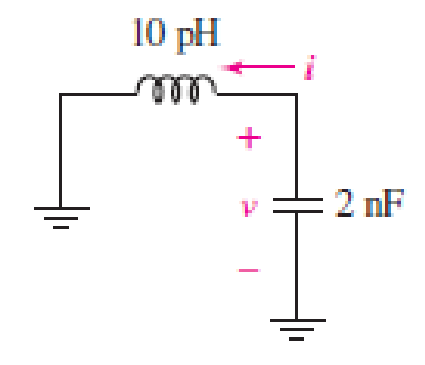
■ FIGURE 9.60
Expert Solution & Answer
Want to see the full answer?
Check out a sample textbook solution
Students have asked these similar questions
when there is in a circuit both of the inductor and the capapcitor, why no need for the inital condition modeling ?
and please give an example for it.
note: type it by keyboard
Task: Using the given charge and discharge values at these discrete points in time, construct
two plots of Voltage (V.) vs. Time (t) for charging and discharging of the capacitor.
ID:
Name of Student:
3.1 RC Circuit
The objective of this part is to study the charging and discharging of a capacitor by
measuring the potential difference (voltage) across the capacitor as a function of time. The
students will also measure the experimental time constant and use it to determine the
experimental value of the capacitance of the capacitor.
Table 1. Voltage-Time Table for Charging Capacitor
Time t(s) Potential Diffèrence V(t)
Time t(s) Potential Diffèrence V(t)
40
1.328 V
OV
5
0.332 V
50
1.386 V
10
60
0.638 V
1.422 V
15
70
0.861 V
1.437 V
20
1.017 V
80
1.448 V
|
25
90
1.458 V
1.131 V
Task: Using your collected Voltage-Time data for discharging, calculate time constant t.
30
1.220 V
100
1.458 V
Show the formulations and data pair you used in the calculation.
If the resistance is given to be equal…
Please help will upvote for sureFor the circuit below:a) What is the maximum current at any time in the circuit?b) Write Equation of capacitor voltage in any time and find the capacitor voltage at t=1msec, t=10msec, t=1sec and t=10sec?d) Draw the capacitor voltage and current signal versus time axis and sign four different time values in (c) on it?
Chapter 9 Solutions
Loose Leaf for Engineering Circuit Analysis Format: Loose-leaf
Ch. 9.1 - A parallel RLC circuit contains a 100 2 resistor...Ch. 9.2 - After being open for a long time, the switch in...Ch. 9.2 - Prob. 3PCh. 9.2 - Prob. 4PCh. 9.3 - (a) Choose R1 in the circuit of Fig. 9.14 so that...Ch. 9.4 - Prob. 6PCh. 9.5 - Prob. 7PCh. 9.5 - Prob. 8PCh. 9.6 - Let is = 10u(t) 20u(t) A in Fig. 9.31. Find (a)...Ch. 9.6 - Let vs = 10 + 20u(t) V in the circuit of Fig....
Ch. 9.7 - Alter the capacitor value and voltage source in...Ch. 9 - For a certain source-free parallel RLC circuit, R...Ch. 9 - Element values of 10 mF and 2 nH are employed in...Ch. 9 - If a parallel RLC circuit is constructed from...Ch. 9 - Prob. 4ECh. 9 - You go to construct the circuit in Exercise 1,...Ch. 9 - A parallel RLC circuit has inductance 2 mH and...Ch. 9 - Prob. 7ECh. 9 - A parallel RLC circuit has R = 1 k, L = 50 mH. and...Ch. 9 - Prob. 9ECh. 9 - Prob. 10ECh. 9 - The current flowing through a 5 resistor in a...Ch. 9 - For the circuit of Fig.9.40, obtain an expression...Ch. 9 - Consider the circuit depicted in Fig. 9.40. (a)...Ch. 9 - With regard to the circuit represented in Fig....Ch. 9 - (a) Assuming the passive sign convention, obtain...Ch. 9 - With regard to the circuit presented in Fig. 9.42,...Ch. 9 - Obtain expressions for the current i(t) and...Ch. 9 - FIGURE 9.43 Replace the 14 resistor in the...Ch. 9 - Design a complete source-free parallel RLC circuit...Ch. 9 - For the circuit represented by Fig. 9.44, the two...Ch. 9 - Prob. 21ECh. 9 - Prob. 22ECh. 9 - A critically damped parallel RLC circuit is...Ch. 9 - A source-free parallel RLC circuit has an initial...Ch. 9 - A critically damped parallel RLC circuit is...Ch. 9 - For the circuit of Fig. 9.45, is(t) = 30u(t) mA....Ch. 9 - Prob. 27ECh. 9 - The circuit of Fig. 9.44 is rebuilt such that the...Ch. 9 - Prob. 29ECh. 9 - Prob. 30ECh. 9 - The source-free circuit depicted in Fig. 9.1 is...Ch. 9 - (a) Graph the current i for the circuit described...Ch. 9 - Analyze the circuit described in Exercise 31 to...Ch. 9 - A source-free parallel RLC circuit has capacitance...Ch. 9 - Prob. 35ECh. 9 - Obtain an expression for vL(t), t 0, for the...Ch. 9 - For the circuit of Fig. 9.47, determine (a) the...Ch. 9 - (a) Design a parallel RLC circuit that provides a...Ch. 9 - The circuit depicted in Fig. 9.48 is just barely...Ch. 9 - When constructing the circuit of Fig. 9.48, you...Ch. 9 - The circuit of Fig. 9.22a is constructed with a...Ch. 9 - Prob. 42ECh. 9 - Prob. 43ECh. 9 - The simple three-element series RLC circuit of...Ch. 9 - Prob. 45ECh. 9 - Prob. 46ECh. 9 - Prob. 47ECh. 9 - With reference to the series RLC circuit of Fig....Ch. 9 - Obtain an expression for i1 as labeled in Fig....Ch. 9 - The circuit in Fig. 9.52 has the switch in...Ch. 9 - For the circuit in Fig. 9.52, determine the value...Ch. 9 - In the series circuit of Fig. 9.53, set R = 1 ....Ch. 9 - Evaluate the derivative of each current and...Ch. 9 - Consider the circuit depicted in Fig. 9.55. If...Ch. 9 - Prob. 55ECh. 9 - In the circuit shown in Fig. 9.56, (a) obtain an...Ch. 9 - Prob. 57ECh. 9 - For the circuit represented in Fig. 9.57, (a)...Ch. 9 - FIGURE 9.57 Replace the 1 resistor in Fig. 9.57...Ch. 9 - A circuit has an inductive load of 2 H, a...Ch. 9 - (a) Adjust the value of the 3 resistor in the...Ch. 9 - Determine expressions for vC(t) and iL(t) in Fig....Ch. 9 - The capacitor in the LC circuit in Fig. 9.60 has...Ch. 9 - Suppose that the switch in the circuit in Fig....Ch. 9 - The capacitor in the circuit of Fig. 9.63 is set...Ch. 9 - The physical behavior of automotive suspension...Ch. 9 - A lossless LC circuit can be used to provide...
Knowledge Booster


Learn more about
Need a deep-dive on the concept behind this application? Look no further. Learn more about this topic, electrical-engineering and related others by exploring similar questions and additional content below.Similar questions
- 9. 7.92. b) Suppose the inductor you chose in part (a) has an initial currentof 10 mA. Write an expression for the current through the inductorfor t≥0.arrow_forwardA Using DC stored energy circuit behavior, determine the the inductor, in ) Calcolate that, both the inductor and eapacitor store energy. capacitor such the amount the value of the the Same of T0on -W- 2002 12V 30.1Harrow_forwardEx : For the circuit shown in the figure below : 1. Find the mathematical expression for the transient behaviour of the voltage across the capacitor as well as the current of the capacitor if the capacitor was initially uncharged and the switch is closed at position 1 when t - o sec . 2. Find the mathematical expression for Vc and is if the switch is moved to position 2 at t = 10msec . 3. Find the mathematical expressions for Vc and ic if the switch is moved to position 3 at t = 20msec 4. Plot the waveforms of the Vc and is obtained from the parts 1 to 3 . R ic 20 kΩ 20 E 12 V C 0.05 uF vc R , 310 ΚΩ Tarrow_forward
- A capacitor C with 1 mF is charged by a constant voltage source (U). Source and capacitor are connected by a resistor R with 10 kQ. To discharge the capacitor the source is replaced by a short. U R charging C R discharging b) Please draw the voltage at the capacitor and the current / over a suitable timeframe. Indicate the time constant at the x-axis. c) How much energy is stored when the voltage is set to 10 V. d) When the constant voltage source is replaced by an alternating voltage source with a sinusoidal output, please derive the magnitude of the transfer function H(jw)=Uin/out when yout is the voltage at the capacitor for w → 0 and w→∞. What kind of filter is obtained? How can the filter characteristics be inverted? e) The voltage source is replaced by a constant current source with an output of 1 mA. Please draw the voltage at the capacitor qualitatively over the time.arrow_forwardThe initial capacitor voltage is 4 V. Switch S1 is closed at t = 0. The charge (in micro C) lost by the capacitor form t = 25 microS to t = 100 microS is:1) 6.992) 8.713) 5.554) 10Please show detailed steps and workarrow_forwardFor the circuit shown find: i) The Voltage across the capacitance, with the polarity as shown, at all times ii)The current through the capacitance at t- time constant +2μ iSec.arrow_forward
- A 0.7-F capacitor is connected in series with a 9-ohm resistor. If the connection is energized from an 11-V DC source, determine which among the following is a differential equation describing the circuit? Let q be the amount of the charge in the circuit at any time t. O A. dq dt O B. dq dt O C. dq dt O D. dq dt + - 9 + 11 + 63 10 9 11 10 63 = = || 10 63 9 11 63 10 11 9arrow_forwardDetermine the prediction model for current at amy time > 0 in an electrical circuit cortaining a 2002 resistor in series with o copacitor of 0.05F, inductor of 10H and 60 volts battery tissume that at t = 0, there is no change in the capacitor. Seres with a Determine the prediction model for current at any time so in an electrical circuit containing a 20π resistor in capacitor of 0.05f, inductor Go volts battery Assume that at t = 0, there is no in the capacitor. 4 lOH and chargearrow_forwardThe voltage across a 5 µF capacitor is known to be Ve = 500te-2500t V for t > 0. a. Find the current through the capacitor for t > 0. Assume the passive sign convention. b. Find the power at the terminals of the capacitor when t = 100 µus. c. Is the capacitor absorbing or delivering power at t = 100 us ? d. Find the energy stored in the capacitor at t = 100 us. e. Find the maximum energy stored in the capacitors and the time when the maximum occurs.arrow_forward
- A 10¯7-F capacitor (100 nanofarads) is charged to 100 V and then disconnected. One can model the charge leakage of the capacitor with a RC circuit with no voltage source and the resistance of the air between the capacitor plates. On a cold dry day, the resistance of the air gap is 3× 10³ Q; on a humid day, the resistance is 8 x 10° Q. How long will it take the capacitor voltage to dissipate to half its original value on each day?arrow_forward9. The voltage across a 2200-pF capacitor is vc(t) = 50 cos (2n10ªt) V. Derive expressions for ic(t) and pc(t). Is the capacitor absorbing power, delivering power, or both? Explain. Solution:arrow_forwardThe capacitor is discharged through a resistor with the resistance R = 10000 Ohm with a relaxation time of 10 ms. What is the capacitance of the capacitor? What is the charge of the capacitor after time 25 ms after the beginning of discharging if the initial charge was 20 nC?arrow_forward
arrow_back_ios
SEE MORE QUESTIONS
arrow_forward_ios
Recommended textbooks for you
 Introductory Circuit Analysis (13th Edition)Electrical EngineeringISBN:9780133923605Author:Robert L. BoylestadPublisher:PEARSON
 Delmar's Standard Textbook Of ElectricityElectrical EngineeringISBN:9781337900348Author:Stephen L. HermanPublisher:Cengage Learning
 Programmable Logic ControllersElectrical EngineeringISBN:9780073373843Author:Frank D. PetruzellaPublisher:McGraw-Hill Education
 Fundamentals of Electric CircuitsElectrical EngineeringISBN:9780078028229Author:Charles K Alexander, Matthew SadikuPublisher:McGraw-Hill Education
 Electric Circuits. (11th Edition)Electrical EngineeringISBN:9780134746968Author:James W. Nilsson, Susan RiedelPublisher:PEARSON
 Engineering ElectromagneticsElectrical EngineeringISBN:9780078028151Author:Hayt, William H. (william Hart), Jr, BUCK, John A.Publisher:Mcgraw-hill Education,
Introductory Circuit Analysis (13th Edition)
Electrical Engineering
ISBN:9780133923605
Author:Robert L. Boylestad
Publisher:PEARSON
Delmar's Standard Textbook Of Electricity
Electrical Engineering
ISBN:9781337900348
Author:Stephen L. Herman
Publisher:Cengage Learning
Programmable Logic Controllers
Electrical Engineering
ISBN:9780073373843
Author:Frank D. Petruzella
Publisher:McGraw-Hill Education
Fundamentals of Electric Circuits
Electrical Engineering
ISBN:9780078028229
Author:Charles K Alexander, Matthew Sadiku
Publisher:McGraw-Hill Education
Electric Circuits. (11th Edition)
Electrical Engineering
ISBN:9780134746968
Author:James W. Nilsson, Susan Riedel
Publisher:PEARSON
Engineering Electromagnetics
Electrical Engineering
ISBN:9780078028151
Author:Hayt, William H. (william Hart), Jr, BUCK, John A.
Publisher:Mcgraw-hill Education,
ENA 9.2(1)(En)(Alex) Sinusoids & Phasors - Explanation with Example 9.1 ,9.2 & PP 9.2; Author: Electrical Engineering Academy;https://www.youtube.com/watch?v=vX_LLNl-ZpU;License: Standard YouTube License, CC-BY
Electrical Engineering: Ch 10 Alternating Voltages & Phasors (8 of 82) What is a Phasor?; Author: Michel van Biezen;https://www.youtube.com/watch?v=2I1tF3ixNg0;License: Standard Youtube License