
Loose Leaf for Engineering Circuit Analysis Format: Loose-leaf
9th Edition
ISBN: 9781259989452
Author: Hayt
Publisher: Mcgraw Hill Publishers
expand_more
expand_more
format_list_bulleted
Videos
Textbook Question
Chapter 9, Problem 56E
In the circuit shown in Fig. 9.56, (a) obtain an expression for iL valid for t > 0 if i1 = 8 − 10u(t) mA, (b) graph the result for 0 ≤ t ≤ 2 ms.
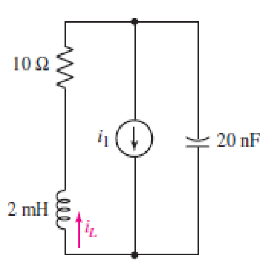
■ FIGURE 9.56
Expert Solution & Answer
Want to see the full answer?
Check out a sample textbook solution
Students have asked these similar questions
The circuit was in steady state at t=0-. The switch closes at t= 0. Write expressions for I. (t>0), and V. (t> 0). Also, sketch I (t> 0) and V. (t> 0).
ve v
t=0
wwwww
252
+m²
^
www
1.5
13
↑ IOA
For the following circuit Vo (0)=5 V andI (0)= -2A(i.e. in the opposite direction to the direction of I (t)) startingthere are conditions.
a) draw the equivalent of the circuit s domain for t>0+ b) expressions Vo(s) and I(s) for t>0+ you can find. c) find the expression Vo (t) d) The Last value theorem of Vo(t)find its value from the expression s domain.
R1
Bt=T.
R3
V1
A
vc(t)
V2
R2
Given
To=2 secs
V1=15 V
V2=11 V
C = 4 F
R1=13 N
R2=10 Q
R3=14 2
and that the voltage across the capacitor is vc(t) = vc(∞) + (Vc(To†) - vC))eT/T for t> To+. Determine the
Note that t=RTHC where RTh is the Thevenin equivalent resistance that the
time constant t in seconds.
capacitor sees after the switch moves from position A to position B at To secs.
Find the time constant t in secs. Round your answer to the nearest single digit decimal place.
Chapter 9 Solutions
Loose Leaf for Engineering Circuit Analysis Format: Loose-leaf
Ch. 9.1 - A parallel RLC circuit contains a 100 2 resistor...Ch. 9.2 - After being open for a long time, the switch in...Ch. 9.2 - Prob. 3PCh. 9.2 - Prob. 4PCh. 9.3 - (a) Choose R1 in the circuit of Fig. 9.14 so that...Ch. 9.4 - Prob. 6PCh. 9.5 - Prob. 7PCh. 9.5 - Prob. 8PCh. 9.6 - Let is = 10u(t) 20u(t) A in Fig. 9.31. Find (a)...Ch. 9.6 - Let vs = 10 + 20u(t) V in the circuit of Fig....
Ch. 9.7 - Alter the capacitor value and voltage source in...Ch. 9 - For a certain source-free parallel RLC circuit, R...Ch. 9 - Element values of 10 mF and 2 nH are employed in...Ch. 9 - If a parallel RLC circuit is constructed from...Ch. 9 - Prob. 4ECh. 9 - You go to construct the circuit in Exercise 1,...Ch. 9 - A parallel RLC circuit has inductance 2 mH and...Ch. 9 - Prob. 7ECh. 9 - A parallel RLC circuit has R = 1 k, L = 50 mH. and...Ch. 9 - Prob. 9ECh. 9 - Prob. 10ECh. 9 - The current flowing through a 5 resistor in a...Ch. 9 - For the circuit of Fig.9.40, obtain an expression...Ch. 9 - Consider the circuit depicted in Fig. 9.40. (a)...Ch. 9 - With regard to the circuit represented in Fig....Ch. 9 - (a) Assuming the passive sign convention, obtain...Ch. 9 - With regard to the circuit presented in Fig. 9.42,...Ch. 9 - Obtain expressions for the current i(t) and...Ch. 9 - FIGURE 9.43 Replace the 14 resistor in the...Ch. 9 - Design a complete source-free parallel RLC circuit...Ch. 9 - For the circuit represented by Fig. 9.44, the two...Ch. 9 - Prob. 21ECh. 9 - Prob. 22ECh. 9 - A critically damped parallel RLC circuit is...Ch. 9 - A source-free parallel RLC circuit has an initial...Ch. 9 - A critically damped parallel RLC circuit is...Ch. 9 - For the circuit of Fig. 9.45, is(t) = 30u(t) mA....Ch. 9 - Prob. 27ECh. 9 - The circuit of Fig. 9.44 is rebuilt such that the...Ch. 9 - Prob. 29ECh. 9 - Prob. 30ECh. 9 - The source-free circuit depicted in Fig. 9.1 is...Ch. 9 - (a) Graph the current i for the circuit described...Ch. 9 - Analyze the circuit described in Exercise 31 to...Ch. 9 - A source-free parallel RLC circuit has capacitance...Ch. 9 - Prob. 35ECh. 9 - Obtain an expression for vL(t), t 0, for the...Ch. 9 - For the circuit of Fig. 9.47, determine (a) the...Ch. 9 - (a) Design a parallel RLC circuit that provides a...Ch. 9 - The circuit depicted in Fig. 9.48 is just barely...Ch. 9 - When constructing the circuit of Fig. 9.48, you...Ch. 9 - The circuit of Fig. 9.22a is constructed with a...Ch. 9 - Prob. 42ECh. 9 - Prob. 43ECh. 9 - The simple three-element series RLC circuit of...Ch. 9 - Prob. 45ECh. 9 - Prob. 46ECh. 9 - Prob. 47ECh. 9 - With reference to the series RLC circuit of Fig....Ch. 9 - Obtain an expression for i1 as labeled in Fig....Ch. 9 - The circuit in Fig. 9.52 has the switch in...Ch. 9 - For the circuit in Fig. 9.52, determine the value...Ch. 9 - In the series circuit of Fig. 9.53, set R = 1 ....Ch. 9 - Evaluate the derivative of each current and...Ch. 9 - Consider the circuit depicted in Fig. 9.55. If...Ch. 9 - Prob. 55ECh. 9 - In the circuit shown in Fig. 9.56, (a) obtain an...Ch. 9 - Prob. 57ECh. 9 - For the circuit represented in Fig. 9.57, (a)...Ch. 9 - FIGURE 9.57 Replace the 1 resistor in Fig. 9.57...Ch. 9 - A circuit has an inductive load of 2 H, a...Ch. 9 - (a) Adjust the value of the 3 resistor in the...Ch. 9 - Determine expressions for vC(t) and iL(t) in Fig....Ch. 9 - The capacitor in the LC circuit in Fig. 9.60 has...Ch. 9 - Suppose that the switch in the circuit in Fig....Ch. 9 - The capacitor in the circuit of Fig. 9.63 is set...Ch. 9 - The physical behavior of automotive suspension...Ch. 9 - A lossless LC circuit can be used to provide...
Knowledge Booster


Learn more about
Need a deep-dive on the concept behind this application? Look no further. Learn more about this topic, electrical-engineering and related others by exploring similar questions and additional content below.Similar questions
- e Y:EA OT ll zain IQ ASIACELL Home Work 3.... TIRE EL ARBOL NAVIDENO Homework ( Due 13-03- 2021) (1) Without using Laplace Transform Obtain an expression for i as labeled in Fig. 9.49 which is valid for all t> 0. 5Ω 500 mH Su(-t) mA 80 Ω 201 1 mF T VC IFIGURE 9.49 Homework ( Due 13- 03- 2021) (2) With using Laplace Transform Obtain an expression for i as labeled in Fig. 9.49 which is valid for all t> 0. 50 500 mH Su(-1) mA 80 0 20i1 1 mF VC IFIGURE 9.49arrow_forwardElectrical Engineering 9. Find the solution to the linear constant coeffcient difference equation (n)= >(n=1)-y(n-2)+ 2u(n) with (-1)=2 and y(-2)=1.arrow_forwardEach student has to prepare a soft copy answer representing the time domain plot of the two voltages {v₁(t)}and {v₂ (t)} that (appears in front of his name) and the phasor diagram of the addition of these two voltages as shown in the table below, then determine the time domain function of the resultant voltage {v3 (t)}: v3 (t) = v₁ (t) + v₂ (t) = V3max Sin(wt F 0) v₂ (t) v₁ (t) 7 sin(wt + 65°) 2 sin(wt + 130°) INarrow_forward
- In the following circuit, the switch SW was left in position 1 for a long time. At time t = 0, the switch is moved to position 2. Draw an s-domain model for the circuit for t≥ 0, and solve for the current, i(t), for t≥ 0. 5V 1412 ym d o m SW LIFE Zl it 81Harrow_forwardThis is a LTI SYSTEM PROBLEM, please answer within 20 minutes. I'm really new at this and I'm having difficulty in getting the answer. Please explain and if possible give the solution also. The problem is The system y(t)=ln[x(t)+A] where A is a constant is The choices are in the photoarrow_forwardic At time t = 0+, the circuit on the right has i, (0+) = 6.5A and vc(0+) = 260V. Determine the following %3| 1/52 uF 4H VL di¿(0*) a) dt 16 ohm b) Characteristic equation of i̟(t) c) Roots of the characteristic equation of i (t) d) Constants K1 and K2 e) i̟(t) for t>Osarrow_forward
- 9- Write the differential equation(s) for the network below with L and R measured in terms of the usual units. v(t) = 100 sin wt if 0 < t < 0.5 L₂ - 1 H R₁ --- 10 L₁ -0.8 H R₂-14Q 0(e)arrow_forward17. Obtain expressions for the current i(t) and voltage v(t) as labeled in the circuit of Fig. 9.43 which are valid for all 1 > 0. 310 mA FIGURE 9.43 1H Xm0 1403 360 μF (0)arrow_forwardASAParrow_forward
- ic At time t = 0+, the circuit on the right has i (0+) = 6.5A and vc(0+) = 260V. Determine the following + 1/52 uF 4H VL di̟(0+) a) VR 16 ohm dt b) Characteristic equation of i̟(t) c) Roots of the characteristic equation of i, (t) d) Constants K1 and K2 e) i̟(t) for t>Os uarrow_forwardThe steady-state error due to unit step input to a type-1 system is: 1. 1/(1+ kp) 2. Zero 3. 1/ Kp 4. Infinityarrow_forwardwww 822 zez 18V(+ +=0 4 H m 252 find i(t) for circuit! use differential dict) +70 in the fol following ~|J F equation approacharrow_forward
arrow_back_ios
SEE MORE QUESTIONS
arrow_forward_ios
Recommended textbooks for you
 Introductory Circuit Analysis (13th Edition)Electrical EngineeringISBN:9780133923605Author:Robert L. BoylestadPublisher:PEARSON
 Delmar's Standard Textbook Of ElectricityElectrical EngineeringISBN:9781337900348Author:Stephen L. HermanPublisher:Cengage Learning
 Programmable Logic ControllersElectrical EngineeringISBN:9780073373843Author:Frank D. PetruzellaPublisher:McGraw-Hill Education
 Fundamentals of Electric CircuitsElectrical EngineeringISBN:9780078028229Author:Charles K Alexander, Matthew SadikuPublisher:McGraw-Hill Education
 Electric Circuits. (11th Edition)Electrical EngineeringISBN:9780134746968Author:James W. Nilsson, Susan RiedelPublisher:PEARSON
 Engineering ElectromagneticsElectrical EngineeringISBN:9780078028151Author:Hayt, William H. (william Hart), Jr, BUCK, John A.Publisher:Mcgraw-hill Education,
Introductory Circuit Analysis (13th Edition)
Electrical Engineering
ISBN:9780133923605
Author:Robert L. Boylestad
Publisher:PEARSON
Delmar's Standard Textbook Of Electricity
Electrical Engineering
ISBN:9781337900348
Author:Stephen L. Herman
Publisher:Cengage Learning
Programmable Logic Controllers
Electrical Engineering
ISBN:9780073373843
Author:Frank D. Petruzella
Publisher:McGraw-Hill Education
Fundamentals of Electric Circuits
Electrical Engineering
ISBN:9780078028229
Author:Charles K Alexander, Matthew Sadiku
Publisher:McGraw-Hill Education
Electric Circuits. (11th Edition)
Electrical Engineering
ISBN:9780134746968
Author:James W. Nilsson, Susan Riedel
Publisher:PEARSON
Engineering Electromagnetics
Electrical Engineering
ISBN:9780078028151
Author:Hayt, William H. (william Hart), Jr, BUCK, John A.
Publisher:Mcgraw-hill Education,
Routh Hurwitz Stability Criterion Basic Worked Example; Author: The Complete Guide to Everything;https://www.youtube.com/watch?v=CzzsR5FT-8U;License: Standard Youtube License