
Loose Leaf for Engineering Circuit Analysis Format: Loose-leaf
9th Edition
ISBN: 9781259989452
Author: Hayt
Publisher: Mcgraw Hill Publishers
expand_more
expand_more
format_list_bulleted
Videos
Textbook Question
Chapter 9.6, Problem 9P
Let is = 10u(−t) − 20u(t) A in Fig. 9.31. Find (a) iL(0−); (b) vC(0+); (c) vR(0+); (d) iL(∞); (e) iL(0.1 ms).
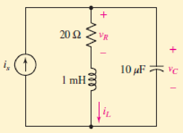
FIGURE 9.31
Expert Solution & Answer
Want to see the full answer?
Check out a sample textbook solution
Students have asked these similar questions
9.39 (System Response) For each circuit of Figure P9.39, let R = 102, C = 1F, and L = 1H as needed.
(d) Find the response if the input is x(t) = u(t).
+
x(t)
L
R
Circuit 4
y(t)
Obtain an equation for vc as labeled in the circuit of Fig. 9.48 valid for all
t > 0.
1 = 0
2i
+ VC
100 2
40 μF
9 V
30 N
90 mH
FIGURE 9.48
47. Vc(t) = -2.08e-1188.4986t
+ 10.48e-233.721t
%3D
ell
The ac bridge shown in Fig. 9.84 is known as a
Maxwell bridge and is used for accurate measurement
of inductance and resistance of a coil in terms of a
standard capacitance C.. Show that when the bridge
is balanced,
R2 R3
R₁
Lx = R₂R3Cs and Rx
=
1.6 ΚΩ,
Find Lx and R, for R₁ = 40 kN, R₂
R3 = 4 kn, and C₂ = 0.45 µF.
R₁
R3
Cs
R₂
AC
meter
R₂
ell
Chapter 9 Solutions
Loose Leaf for Engineering Circuit Analysis Format: Loose-leaf
Ch. 9.1 - A parallel RLC circuit contains a 100 2 resistor...Ch. 9.2 - After being open for a long time, the switch in...Ch. 9.2 - Prob. 3PCh. 9.2 - Prob. 4PCh. 9.3 - (a) Choose R1 in the circuit of Fig. 9.14 so that...Ch. 9.4 - Prob. 6PCh. 9.5 - Prob. 7PCh. 9.5 - Prob. 8PCh. 9.6 - Let is = 10u(t) 20u(t) A in Fig. 9.31. Find (a)...Ch. 9.6 - Let vs = 10 + 20u(t) V in the circuit of Fig....
Ch. 9.7 - Alter the capacitor value and voltage source in...Ch. 9 - For a certain source-free parallel RLC circuit, R...Ch. 9 - Element values of 10 mF and 2 nH are employed in...Ch. 9 - If a parallel RLC circuit is constructed from...Ch. 9 - Prob. 4ECh. 9 - You go to construct the circuit in Exercise 1,...Ch. 9 - A parallel RLC circuit has inductance 2 mH and...Ch. 9 - Prob. 7ECh. 9 - A parallel RLC circuit has R = 1 k, L = 50 mH. and...Ch. 9 - Prob. 9ECh. 9 - Prob. 10ECh. 9 - The current flowing through a 5 resistor in a...Ch. 9 - For the circuit of Fig.9.40, obtain an expression...Ch. 9 - Consider the circuit depicted in Fig. 9.40. (a)...Ch. 9 - With regard to the circuit represented in Fig....Ch. 9 - (a) Assuming the passive sign convention, obtain...Ch. 9 - With regard to the circuit presented in Fig. 9.42,...Ch. 9 - Obtain expressions for the current i(t) and...Ch. 9 - FIGURE 9.43 Replace the 14 resistor in the...Ch. 9 - Design a complete source-free parallel RLC circuit...Ch. 9 - For the circuit represented by Fig. 9.44, the two...Ch. 9 - Prob. 21ECh. 9 - Prob. 22ECh. 9 - A critically damped parallel RLC circuit is...Ch. 9 - A source-free parallel RLC circuit has an initial...Ch. 9 - A critically damped parallel RLC circuit is...Ch. 9 - For the circuit of Fig. 9.45, is(t) = 30u(t) mA....Ch. 9 - Prob. 27ECh. 9 - The circuit of Fig. 9.44 is rebuilt such that the...Ch. 9 - Prob. 29ECh. 9 - Prob. 30ECh. 9 - The source-free circuit depicted in Fig. 9.1 is...Ch. 9 - (a) Graph the current i for the circuit described...Ch. 9 - Analyze the circuit described in Exercise 31 to...Ch. 9 - A source-free parallel RLC circuit has capacitance...Ch. 9 - Prob. 35ECh. 9 - Obtain an expression for vL(t), t 0, for the...Ch. 9 - For the circuit of Fig. 9.47, determine (a) the...Ch. 9 - (a) Design a parallel RLC circuit that provides a...Ch. 9 - The circuit depicted in Fig. 9.48 is just barely...Ch. 9 - When constructing the circuit of Fig. 9.48, you...Ch. 9 - The circuit of Fig. 9.22a is constructed with a...Ch. 9 - Prob. 42ECh. 9 - Prob. 43ECh. 9 - The simple three-element series RLC circuit of...Ch. 9 - Prob. 45ECh. 9 - Prob. 46ECh. 9 - Prob. 47ECh. 9 - With reference to the series RLC circuit of Fig....Ch. 9 - Obtain an expression for i1 as labeled in Fig....Ch. 9 - The circuit in Fig. 9.52 has the switch in...Ch. 9 - For the circuit in Fig. 9.52, determine the value...Ch. 9 - In the series circuit of Fig. 9.53, set R = 1 ....Ch. 9 - Evaluate the derivative of each current and...Ch. 9 - Consider the circuit depicted in Fig. 9.55. If...Ch. 9 - Prob. 55ECh. 9 - In the circuit shown in Fig. 9.56, (a) obtain an...Ch. 9 - Prob. 57ECh. 9 - For the circuit represented in Fig. 9.57, (a)...Ch. 9 - FIGURE 9.57 Replace the 1 resistor in Fig. 9.57...Ch. 9 - A circuit has an inductive load of 2 H, a...Ch. 9 - (a) Adjust the value of the 3 resistor in the...Ch. 9 - Determine expressions for vC(t) and iL(t) in Fig....Ch. 9 - The capacitor in the LC circuit in Fig. 9.60 has...Ch. 9 - Suppose that the switch in the circuit in Fig....Ch. 9 - The capacitor in the circuit of Fig. 9.63 is set...Ch. 9 - The physical behavior of automotive suspension...Ch. 9 - A lossless LC circuit can be used to provide...
Knowledge Booster


Learn more about
Need a deep-dive on the concept behind this application? Look no further. Learn more about this topic, electrical-engineering and related others by exploring similar questions and additional content below.Similar questions
- 47. Obtain an equation for vc as labeled in the circuit of Fig. 9.50 valid for all t> 0. t = 0 2i + VC 100 2 X. 40 µF 30 Ω 90 mH I FIGURE 9.50 Vc(t) = -2.08e-1188.4986t + 10.48e-233.721tarrow_forward9.pdf - Adobe Acrobat Reader DC (64-bit) ndow Help FINAL EP QP_SEM . x Sign In 10 / 12 116% Search Combine PDF Export PDF A capacitor is charged with 50 mC in a time of 20 uS. If the energy stored in the capacitor is 5 J, Edit PDF find (i) voltage across the capacitor, (ii) current through the capacitor and (iii) value of capacitance. Create PDF EComment Combine Files E0 Organize Pag Delete, insert, extract and rotate pages. Try now Convert, edit and e-sign Parrow_forwardCalculate transient voltage uC(t) after commutation in circuit shown in Fig. 9.12. Assume: R1=1Ω, R2=2Ω,L=1H, C=1F, e(t)=10sin(t).arrow_forward
- H = 3RM2cos(9ft) where f = frequency, t = time, and the remaining variables are either proportionality constants or material constants. What is the maximum value H could have (algebraic answer)arrow_forwardPart (0) Prior to coming to the lab, calculate the theoretical parameter values of S₁, S2, a, wd and T (time period) for the RLC circuit shown in Figure 9.1 and record them in Table 9.1 + 2Vp-p ( Figure 9.1: Series RLC Circuit α Rtot 2009 m Wo 100mH Table 9.1: Theoretical Parameter Values of Figure 9.1 Parameter Calculated Value Wd S₁ S₂ T 39 0.01μFarrow_forwardObtain an equation for vc as labeled in the circuit of Fig. 9.48 valid for all t > 0. t = 0 2i + VC 100 Q 40 µF 9 V (* 30 Q 90 mH FIGURE 9.48arrow_forward
- 3. If the switch changes position (from b-c to a-b) at t-0, find the capacitor voltage ve(t) for t20. Calculate the energy stored in the capacitor at t-10ms. y (12) 10 (2) 5 (1) 10y (V)( 2y (2) 5 (A) 5 (mF) vat)arrow_forward²√² +2 Q1: let the sequence x(n)= 1 + 2n 0 3≤n≤4 −1≤n≤0 other wise 1-y₁(n)=2x(2n+2) 2-y₂(n)= p(n)+x(n) 3- can you express the signal in terms of signals 8(n). draw the followingarrow_forwardwww 822 zez 18V(+ +=0 4 H m 252 find i(t) for circuit! use differential dict) +70 in the fol following ~|J F equation approacharrow_forward
- FIGURE 9.45 27. The inductor in the circuit of Fig. 9.43 is changed such that the circuit response is now critically damped. (a) Determine the new inductor value. (b) Calculate the energy stored in both the inductor and the capacitor at t = 10 ms. 30 787arrow_forwardVR7NXRXIPNJHM Join a Meeting - Zo.O movies.awesomese.. ndll al O ispe v e 6 This option This option Question* 2s If F(s) then (s+1)2 f(t) = te* +et f(t) = 2et- 2tet This option O This option ft) = - sin (3t) f(t) = t sin (3t) O This option O This optionarrow_forwardDraw the root locus of the system given in the figure for K > 0.arrow_forward
arrow_back_ios
SEE MORE QUESTIONS
arrow_forward_ios
Recommended textbooks for you
 Introductory Circuit Analysis (13th Edition)Electrical EngineeringISBN:9780133923605Author:Robert L. BoylestadPublisher:PEARSON
 Delmar's Standard Textbook Of ElectricityElectrical EngineeringISBN:9781337900348Author:Stephen L. HermanPublisher:Cengage Learning
 Programmable Logic ControllersElectrical EngineeringISBN:9780073373843Author:Frank D. PetruzellaPublisher:McGraw-Hill Education
 Fundamentals of Electric CircuitsElectrical EngineeringISBN:9780078028229Author:Charles K Alexander, Matthew SadikuPublisher:McGraw-Hill Education
 Electric Circuits. (11th Edition)Electrical EngineeringISBN:9780134746968Author:James W. Nilsson, Susan RiedelPublisher:PEARSON
 Engineering ElectromagneticsElectrical EngineeringISBN:9780078028151Author:Hayt, William H. (william Hart), Jr, BUCK, John A.Publisher:Mcgraw-hill Education,
Introductory Circuit Analysis (13th Edition)
Electrical Engineering
ISBN:9780133923605
Author:Robert L. Boylestad
Publisher:PEARSON
Delmar's Standard Textbook Of Electricity
Electrical Engineering
ISBN:9781337900348
Author:Stephen L. Herman
Publisher:Cengage Learning
Programmable Logic Controllers
Electrical Engineering
ISBN:9780073373843
Author:Frank D. Petruzella
Publisher:McGraw-Hill Education
Fundamentals of Electric Circuits
Electrical Engineering
ISBN:9780078028229
Author:Charles K Alexander, Matthew Sadiku
Publisher:McGraw-Hill Education
Electric Circuits. (11th Edition)
Electrical Engineering
ISBN:9780134746968
Author:James W. Nilsson, Susan Riedel
Publisher:PEARSON
Engineering Electromagnetics
Electrical Engineering
ISBN:9780078028151
Author:Hayt, William H. (william Hart), Jr, BUCK, John A.
Publisher:Mcgraw-hill Education,
02 - Sinusoidal AC Voltage Sources in Circuits, Part 1; Author: Math and Science;https://www.youtube.com/watch?v=8zMiIHVMfaw;License: Standard Youtube License