
Loose Leaf for Engineering Circuit Analysis Format: Loose-leaf
9th Edition
ISBN: 9781259989452
Author: Hayt
Publisher: Mcgraw Hill Publishers
expand_more
expand_more
format_list_bulleted
Concept explainers
Videos
Textbook Question
Chapter 9, Problem 61E
(a) Adjust the value of the 3 Ω resistor in the circuit represented in Fig. 9.58 to obtain a “just barely” overdamped response. Using the new resistor value, (b) determine expressions for vC(t) and iL(t) for t > 0, and (c) graph the energy stored in the capacitor and inductor for t > 0.
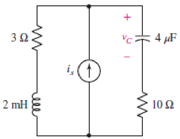
■ FIGURE 9.58
Expert Solution & Answer
Want to see the full answer?
Check out a sample textbook solution
Students have asked these similar questions
The ac bridge shown in Fig. 9.84 is known as a
Maxwell bridge and is used for accurate measurement
of inductance and resistance of a coil in terms of a
standard capacitance C.. Show that when the bridge
is balanced,
R2 R3
R₁
Lx = R₂R3Cs and Rx
=
1.6 ΚΩ,
Find Lx and R, for R₁ = 40 kN, R₂
R3 = 4 kn, and C₂ = 0.45 µF.
R₁
R3
Cs
R₂
AC
meter
R₂
ell
The natural response is the behavior of a circuit for a long time when an external excitation is applied.
True
False
Part (0) Prior to coming to the lab, calculate the theoretical parameter values of S₁, S2, a, wd and T
(time period) for the RLC circuit shown in Figure 9.1 and record them in Table 9.1
+
2Vp-p (
Figure 9.1: Series RLC Circuit
α
Rtot 2009
m
Wo
100mH
Table 9.1: Theoretical Parameter Values of Figure 9.1
Parameter Calculated Value
Wd
S₁
S₂
T
39
0.01μF
Chapter 9 Solutions
Loose Leaf for Engineering Circuit Analysis Format: Loose-leaf
Ch. 9.1 - A parallel RLC circuit contains a 100 2 resistor...Ch. 9.2 - After being open for a long time, the switch in...Ch. 9.2 - Prob. 3PCh. 9.2 - Prob. 4PCh. 9.3 - (a) Choose R1 in the circuit of Fig. 9.14 so that...Ch. 9.4 - Prob. 6PCh. 9.5 - Prob. 7PCh. 9.5 - Prob. 8PCh. 9.6 - Let is = 10u(t) 20u(t) A in Fig. 9.31. Find (a)...Ch. 9.6 - Let vs = 10 + 20u(t) V in the circuit of Fig....
Ch. 9.7 - Alter the capacitor value and voltage source in...Ch. 9 - For a certain source-free parallel RLC circuit, R...Ch. 9 - Element values of 10 mF and 2 nH are employed in...Ch. 9 - If a parallel RLC circuit is constructed from...Ch. 9 - Prob. 4ECh. 9 - You go to construct the circuit in Exercise 1,...Ch. 9 - A parallel RLC circuit has inductance 2 mH and...Ch. 9 - Prob. 7ECh. 9 - A parallel RLC circuit has R = 1 k, L = 50 mH. and...Ch. 9 - Prob. 9ECh. 9 - Prob. 10ECh. 9 - The current flowing through a 5 resistor in a...Ch. 9 - For the circuit of Fig.9.40, obtain an expression...Ch. 9 - Consider the circuit depicted in Fig. 9.40. (a)...Ch. 9 - With regard to the circuit represented in Fig....Ch. 9 - (a) Assuming the passive sign convention, obtain...Ch. 9 - With regard to the circuit presented in Fig. 9.42,...Ch. 9 - Obtain expressions for the current i(t) and...Ch. 9 - FIGURE 9.43 Replace the 14 resistor in the...Ch. 9 - Design a complete source-free parallel RLC circuit...Ch. 9 - For the circuit represented by Fig. 9.44, the two...Ch. 9 - Prob. 21ECh. 9 - Prob. 22ECh. 9 - A critically damped parallel RLC circuit is...Ch. 9 - A source-free parallel RLC circuit has an initial...Ch. 9 - A critically damped parallel RLC circuit is...Ch. 9 - For the circuit of Fig. 9.45, is(t) = 30u(t) mA....Ch. 9 - Prob. 27ECh. 9 - The circuit of Fig. 9.44 is rebuilt such that the...Ch. 9 - Prob. 29ECh. 9 - Prob. 30ECh. 9 - The source-free circuit depicted in Fig. 9.1 is...Ch. 9 - (a) Graph the current i for the circuit described...Ch. 9 - Analyze the circuit described in Exercise 31 to...Ch. 9 - A source-free parallel RLC circuit has capacitance...Ch. 9 - Prob. 35ECh. 9 - Obtain an expression for vL(t), t 0, for the...Ch. 9 - For the circuit of Fig. 9.47, determine (a) the...Ch. 9 - (a) Design a parallel RLC circuit that provides a...Ch. 9 - The circuit depicted in Fig. 9.48 is just barely...Ch. 9 - When constructing the circuit of Fig. 9.48, you...Ch. 9 - The circuit of Fig. 9.22a is constructed with a...Ch. 9 - Prob. 42ECh. 9 - Prob. 43ECh. 9 - The simple three-element series RLC circuit of...Ch. 9 - Prob. 45ECh. 9 - Prob. 46ECh. 9 - Prob. 47ECh. 9 - With reference to the series RLC circuit of Fig....Ch. 9 - Obtain an expression for i1 as labeled in Fig....Ch. 9 - The circuit in Fig. 9.52 has the switch in...Ch. 9 - For the circuit in Fig. 9.52, determine the value...Ch. 9 - In the series circuit of Fig. 9.53, set R = 1 ....Ch. 9 - Evaluate the derivative of each current and...Ch. 9 - Consider the circuit depicted in Fig. 9.55. If...Ch. 9 - Prob. 55ECh. 9 - In the circuit shown in Fig. 9.56, (a) obtain an...Ch. 9 - Prob. 57ECh. 9 - For the circuit represented in Fig. 9.57, (a)...Ch. 9 - FIGURE 9.57 Replace the 1 resistor in Fig. 9.57...Ch. 9 - A circuit has an inductive load of 2 H, a...Ch. 9 - (a) Adjust the value of the 3 resistor in the...Ch. 9 - Determine expressions for vC(t) and iL(t) in Fig....Ch. 9 - The capacitor in the LC circuit in Fig. 9.60 has...Ch. 9 - Suppose that the switch in the circuit in Fig....Ch. 9 - The capacitor in the circuit of Fig. 9.63 is set...Ch. 9 - The physical behavior of automotive suspension...Ch. 9 - A lossless LC circuit can be used to provide...
Additional Engineering Textbook Solutions
Find more solutions based on key concepts
How many coulombs do 93.8 1016 electrons represent?
Principles Of Electric Circuits
Design an ideal inverting op-amp circuit such that the voltage gain is Av=25 . The maximum current in any resis...
Microelectronics: Circuit Analysis and Design
For the “tank” circuit in Fig. 14.79, find the resonant frequency.
Figure 14.79
For Probs. 14.39, 14.71, and 1...
Fundamentals of Electric Circuits
Electric power systems provide energy in a variety of commercial and industrial settings. Make a list of system...
Principles and Applications of Electrical Engineering
Analog Voltmeter Design Figure P2-98(a) shows a voltmeter circuit consisting of a D'Arsonval meter, two series ...
ANALYSIS+DESIGN OF LINEAR CIRCUITS(LL)
Three point charges of equal magnitude q, that will yield a zero net electric field at the origin.
Engineering Electromagnetics
Knowledge Booster


Learn more about
Need a deep-dive on the concept behind this application? Look no further. Learn more about this topic, electrical-engineering and related others by exploring similar questions and additional content below.Similar questions
- For the circuit in Figure 3 the switch is in the left position for several minutes: (a) Find the Initlal voltage, V, on the capacitor just before the switch is flipped (b) Find an expression v(t) that describes the voltage across the 20 N resistor after the switch has been Figure 3 U 09 flipped to the right NOTE: Remember what we said in class: use a Circuit-Specific Equation to get a value you know. Then solve for whatever else the problem asks for +50 µF 380 0 20 2arrow_forwardObtain an equation for vc as labeled in the circuit of Fig. 9.48 valid for all t > 0. 1 = 0 2i + VC 100 2 40 μF 9 V 30 N 90 mH FIGURE 9.48 47. Vc(t) = -2.08e-1188.4986t + 10.48e-233.721t %3D ellarrow_forwardFor the circuit shown below, an uncharged capacitor is connected through switch Q to Position 1 at t = 0 s. The time taken for the capacitor voltage to reach 80 % of source voltage when switch Q is in Position 1 is __ seconds.arrow_forward
- Assume that the circuit has been connected for a very long time.Note: X= 1 a.) As time approaches infinity, what will happen to the capacitor and inductor?b.) From your answer in a.) draw the equivalent circuit ( label appropriately)c.) From your circuit in b.) determine the" steady state" or " final" values of Vc, Ic,Il, Vl Please assist me with this assignment problem if I may ask please make the solution complete or step by step. thank you very much.arrow_forwardAssignment: RL & RC Circuits. R Figure 1: RL Circuit 1. In an RL series circuit containing only a resistor and inductor, Kirchhop's second law states that the sum of the voltage drop across the inductor(Ldi/dt) and the voltage drop across the resistor (iR) is the same as the impressed voltage (E(t)) on the circuit. The current i(t), called the response of the system, is governed by a differential equation di L + Ri = E(t) 'dt where L and R are constants known as inductance and the resistance respectively. Based on the above equation, solve the following: (a) A 12-volt battery is connected to a series in which the inductance is 0.5 henry and the resistance is 10 ohms. Determine the current i if the initial current is zero. Then determine the steady-state current for the system. Ans: i(t) = (1 –e-201) %3D (b) An electromotive force 0 20 120, E(t) = { 0, is applied to an LR series circuit in which the inductance is 20 henry and the resistance is 2 ohms. Find the current i(t) if i(0) = 0.…arrow_forward3. We have seen that in a series RLC circuit, Kirchoff's voltage law (VR +VL + Vc = Vs, where Vs is the supply voltage) leads to a 2nd order differential equation for the current I(t). Let us now consider a parallel RLC circuit consisting of a 5 H inductor, a 10 F capacitor, and a 0.5 N resistor. At time t = 0 s, there is a supply current Is of 5 A. The supply voltage Vs is common to all three components. Kirchoff's current law states that IR + IL + Iç = Is.arrow_forward
- The voltage at terminal of the inductor in circuit is shown in figure. The inductor current I is known to be zero for t≤0. Plot I versus t for 0≤tarrow_forward9:01 For the circuit shown, the current flow thro... For the circuit shown, the current flow through R₁ is: A 8 A Mc Graw Hill +|+ O N O R1 R₁ = Multiple Choice 552 4.8 A. 0.8 A. ㅁㅁ w DOD DOO R2 = 1092 F4 V 24 V < Prev F5 R3 38 of 75 F6 *** 4 Nearrow_forwardAs displayed in attachment figure and LC circuit can be modeled by the following system of differential equations as attachment. Where L = inductance (H), t = time (s), i = current (A), and C = capacitance (F). Assuming that a solution is of the form = Ij sin (wt), determine the eigenvalues and eigenvectors for this system using Faddeev-Leverrier Method and Power Method with L = 1 H and C = 0.25 C. Draw the network, illustrating how the currents oscillate in their primary nodes. Assume initial value for power method.arrow_forward
- The current in the circuit in the following figure is known to be i B₁e -2000t cos1500t + B₂e-2000t sin1500t, t ≥ 0. The capacitor has a value of 80 nF; the initial value of the current is 6.5 mA; and the initial voltage on the capacitor is -21 V.(Figure 1) Figure R www D L Io 1 of 1 > + Vo Correct Here we learn how to determine the value of B₁ in the underdamped natural response of a series RLC circuit. Part D Find the value of B2. Express your answer with the appropriate units. ▾ View Available Hint(s) Hint 1. How to determine B2 Find a and wa from the expression for i. Use KVL to determine the initial voltage across the inductor and calculate the initial value of di/dt. Use the obtained values and the value of B₁ to find B2. B₂= 10.5 Submit 01 Provide Feedback mA Previous Answers Request Answer X Incorrect; Try Again; 2 attempts remaining Next >arrow_forwardQuestion 6 Given a formula for i(t)=10sin(200pit+pi/8) across a capacitor (C=5microfarads). Find the expression of the voltage v(t) across the capcitor. Where Im confused is after integrating the Current and dividing it by C=5microfarads do we need to add +K at the end of the expression? Full explainthe this question very fast solution sent me step by step Don't ignore any part all part work u Text typing work only not allow paper work ......arrow_forwardCan you help me solve this? For two capacitors C1, C2 in series, with initial voltages (at t = 0-) V01 and V02, respectively, derive the instantaneous voltages v1(t) across C1 and v2(t) across C2 for t ≥ 0+in terms of C1, C2, V01, and V02.arrow_forward
arrow_back_ios
SEE MORE QUESTIONS
arrow_forward_ios
Recommended textbooks for you
 Introductory Circuit Analysis (13th Edition)Electrical EngineeringISBN:9780133923605Author:Robert L. BoylestadPublisher:PEARSON
 Delmar's Standard Textbook Of ElectricityElectrical EngineeringISBN:9781337900348Author:Stephen L. HermanPublisher:Cengage Learning
 Programmable Logic ControllersElectrical EngineeringISBN:9780073373843Author:Frank D. PetruzellaPublisher:McGraw-Hill Education
 Fundamentals of Electric CircuitsElectrical EngineeringISBN:9780078028229Author:Charles K Alexander, Matthew SadikuPublisher:McGraw-Hill Education
 Electric Circuits. (11th Edition)Electrical EngineeringISBN:9780134746968Author:James W. Nilsson, Susan RiedelPublisher:PEARSON
 Engineering ElectromagneticsElectrical EngineeringISBN:9780078028151Author:Hayt, William H. (william Hart), Jr, BUCK, John A.Publisher:Mcgraw-hill Education,
Introductory Circuit Analysis (13th Edition)
Electrical Engineering
ISBN:9780133923605
Author:Robert L. Boylestad
Publisher:PEARSON
Delmar's Standard Textbook Of Electricity
Electrical Engineering
ISBN:9781337900348
Author:Stephen L. Herman
Publisher:Cengage Learning
Programmable Logic Controllers
Electrical Engineering
ISBN:9780073373843
Author:Frank D. Petruzella
Publisher:McGraw-Hill Education
Fundamentals of Electric Circuits
Electrical Engineering
ISBN:9780078028229
Author:Charles K Alexander, Matthew Sadiku
Publisher:McGraw-Hill Education
Electric Circuits. (11th Edition)
Electrical Engineering
ISBN:9780134746968
Author:James W. Nilsson, Susan Riedel
Publisher:PEARSON
Engineering Electromagnetics
Electrical Engineering
ISBN:9780078028151
Author:Hayt, William H. (william Hart), Jr, BUCK, John A.
Publisher:Mcgraw-hill Education,
ENA 9.2(1)(En)(Alex) Sinusoids & Phasors - Explanation with Example 9.1 ,9.2 & PP 9.2; Author: Electrical Engineering Academy;https://www.youtube.com/watch?v=vX_LLNl-ZpU;License: Standard YouTube License, CC-BY
Electrical Engineering: Ch 10 Alternating Voltages & Phasors (8 of 82) What is a Phasor?; Author: Michel van Biezen;https://www.youtube.com/watch?v=2I1tF3ixNg0;License: Standard Youtube License