
Loose Leaf for Engineering Circuit Analysis Format: Loose-leaf
9th Edition
ISBN: 9781259989452
Author: Hayt
Publisher: Mcgraw Hill Publishers
expand_more
expand_more
format_list_bulleted
Videos
Textbook Question
Chapter 9.6, Problem 10P
Let vs = 10 + 20u(t) V in the circuit of Fig. 9.34. Find (a) iL (0); (b) vC(0); (c)
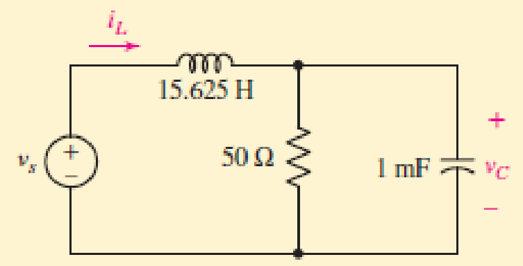
FIGURE 9.34
Expert Solution & Answer
Want to see the full answer?
Check out a sample textbook solution
Students have asked these similar questions
Find v,(t) in the circuit of Fig. 9.56 if the current i,
through the 1-N resistor is 0.5 sin 200t A.
i,
2Ω
1Ω
Vs
j2 Q
-j1 N
ll
solve for the dc quantities, VB(Q1), and VB(Q2)
Electrical Engineering
9. Find the solution to the linear constant coeffcient difference equation
(n)= >(n=1)-y(n-2)+ 2u(n) with
(-1)=2
and y(-2)=1.
Chapter 9 Solutions
Loose Leaf for Engineering Circuit Analysis Format: Loose-leaf
Ch. 9.1 - A parallel RLC circuit contains a 100 2 resistor...Ch. 9.2 - After being open for a long time, the switch in...Ch. 9.2 - Prob. 3PCh. 9.2 - Prob. 4PCh. 9.3 - (a) Choose R1 in the circuit of Fig. 9.14 so that...Ch. 9.4 - Prob. 6PCh. 9.5 - Prob. 7PCh. 9.5 - Prob. 8PCh. 9.6 - Let is = 10u(t) 20u(t) A in Fig. 9.31. Find (a)...Ch. 9.6 - Let vs = 10 + 20u(t) V in the circuit of Fig....
Ch. 9.7 - Alter the capacitor value and voltage source in...Ch. 9 - For a certain source-free parallel RLC circuit, R...Ch. 9 - Element values of 10 mF and 2 nH are employed in...Ch. 9 - If a parallel RLC circuit is constructed from...Ch. 9 - Prob. 4ECh. 9 - You go to construct the circuit in Exercise 1,...Ch. 9 - A parallel RLC circuit has inductance 2 mH and...Ch. 9 - Prob. 7ECh. 9 - A parallel RLC circuit has R = 1 k, L = 50 mH. and...Ch. 9 - Prob. 9ECh. 9 - Prob. 10ECh. 9 - The current flowing through a 5 resistor in a...Ch. 9 - For the circuit of Fig.9.40, obtain an expression...Ch. 9 - Consider the circuit depicted in Fig. 9.40. (a)...Ch. 9 - With regard to the circuit represented in Fig....Ch. 9 - (a) Assuming the passive sign convention, obtain...Ch. 9 - With regard to the circuit presented in Fig. 9.42,...Ch. 9 - Obtain expressions for the current i(t) and...Ch. 9 - FIGURE 9.43 Replace the 14 resistor in the...Ch. 9 - Design a complete source-free parallel RLC circuit...Ch. 9 - For the circuit represented by Fig. 9.44, the two...Ch. 9 - Prob. 21ECh. 9 - Prob. 22ECh. 9 - A critically damped parallel RLC circuit is...Ch. 9 - A source-free parallel RLC circuit has an initial...Ch. 9 - A critically damped parallel RLC circuit is...Ch. 9 - For the circuit of Fig. 9.45, is(t) = 30u(t) mA....Ch. 9 - Prob. 27ECh. 9 - The circuit of Fig. 9.44 is rebuilt such that the...Ch. 9 - Prob. 29ECh. 9 - Prob. 30ECh. 9 - The source-free circuit depicted in Fig. 9.1 is...Ch. 9 - (a) Graph the current i for the circuit described...Ch. 9 - Analyze the circuit described in Exercise 31 to...Ch. 9 - A source-free parallel RLC circuit has capacitance...Ch. 9 - Prob. 35ECh. 9 - Obtain an expression for vL(t), t 0, for the...Ch. 9 - For the circuit of Fig. 9.47, determine (a) the...Ch. 9 - (a) Design a parallel RLC circuit that provides a...Ch. 9 - The circuit depicted in Fig. 9.48 is just barely...Ch. 9 - When constructing the circuit of Fig. 9.48, you...Ch. 9 - The circuit of Fig. 9.22a is constructed with a...Ch. 9 - Prob. 42ECh. 9 - Prob. 43ECh. 9 - The simple three-element series RLC circuit of...Ch. 9 - Prob. 45ECh. 9 - Prob. 46ECh. 9 - Prob. 47ECh. 9 - With reference to the series RLC circuit of Fig....Ch. 9 - Obtain an expression for i1 as labeled in Fig....Ch. 9 - The circuit in Fig. 9.52 has the switch in...Ch. 9 - For the circuit in Fig. 9.52, determine the value...Ch. 9 - In the series circuit of Fig. 9.53, set R = 1 ....Ch. 9 - Evaluate the derivative of each current and...Ch. 9 - Consider the circuit depicted in Fig. 9.55. If...Ch. 9 - Prob. 55ECh. 9 - In the circuit shown in Fig. 9.56, (a) obtain an...Ch. 9 - Prob. 57ECh. 9 - For the circuit represented in Fig. 9.57, (a)...Ch. 9 - FIGURE 9.57 Replace the 1 resistor in Fig. 9.57...Ch. 9 - A circuit has an inductive load of 2 H, a...Ch. 9 - (a) Adjust the value of the 3 resistor in the...Ch. 9 - Determine expressions for vC(t) and iL(t) in Fig....Ch. 9 - The capacitor in the LC circuit in Fig. 9.60 has...Ch. 9 - Suppose that the switch in the circuit in Fig....Ch. 9 - The capacitor in the circuit of Fig. 9.63 is set...Ch. 9 - The physical behavior of automotive suspension...Ch. 9 - A lossless LC circuit can be used to provide...
Knowledge Booster


Learn more about
Need a deep-dive on the concept behind this application? Look no further. Learn more about this topic, electrical-engineering and related others by exploring similar questions and additional content below.Similar questions
- Obtain an equation for vc as labeled in the circuit of Fig. 9.48 valid for all t > 0. 1 = 0 2i + VC 100 2 40 μF 9 V 30 N 90 mH FIGURE 9.48 47. Vc(t) = -2.08e-1188.4986t + 10.48e-233.721t %3D ellarrow_forward47. Obtain an equation for vc as labeled in the circuit of Fig. 9.50 valid for all t> 0. t = 0 2i + VC 100 2 X. 40 µF 30 Ω 90 mH I FIGURE 9.50 Vc(t) = -2.08e-1188.4986t + 10.48e-233.721tarrow_forwardExample 9.2-1 (See Example 9.2-1 in the textbook for the solution to a similar problem.) 0.25H 9Ω Ω 0.20H This circuit can be represented by the differential equation d i2 + aoi2. dvs b1 dt + + a1 dt dt2 Determine the values of the coefficients b,, a, and a- |and a, = a1 = b1 Click if you would like to Show Work for this question: Open Show Workarrow_forward
- Obtain an equation for vc as labeled in the circuit of Fig. 9.48 valid for all t > 0. t = 0 2i + VC 100 Q 40 µF 9 V (* 30 Q 90 mH FIGURE 9.48arrow_forward9.39 (System Response) For each circuit of Figure P9.39, let R = 102, C = 1F, and L = 1H as needed. (d) Find the response if the input is x(t) = u(t). + x(t) L R Circuit 4 y(t)arrow_forwardDue to a manufacturing error, resistor RP has appeared in series with the emitter of Q1 in Fig. 9.62. If I1 is half of its nominal value, express the value of RP in terms of other circuit parameters. Assume QREF and Q1 are identical and β≫ 1.arrow_forward
- Part (0) Prior to coming to the lab, calculate the theoretical parameter values of S₁, S2, a, wd and T (time period) for the RLC circuit shown in Figure 9.1 and record them in Table 9.1 + 2Vp-p ( Figure 9.1: Series RLC Circuit α Rtot 2009 m Wo 100mH Table 9.1: Theoretical Parameter Values of Figure 9.1 Parameter Calculated Value Wd S₁ S₂ T 39 0.01μFarrow_forwarduo 10:16 A docs.google.com 65% zain IQ l. bl 10 Q1: As the figure Shawn for t3D0, switch 1 is closed and switch 2 is closed 4sec later, find i(t) for t>0 and i * for t=2s, and t=5s 1=0 62 1= 4 40 V 5H 10 v i(i(t)={(0 t<0, 4(1-e^(-2t) ) Osts4, 2.727+1.273e^(-1.466(t-4) t24) )}A ,3.93A, O 3.022A i(i(t)={(0 ts0, 4(1-e^(-2t) ) Osts4, 2.727+1.273e^(-1.466(t-4) t24) )}A ,3.93A, 4.022A i(i(t)={(0 t<0, 4(1-e^(-2t) ) 0arrow_forwardCalculate transient voltage uC(t) after commutation in circuit shown in Fig. 9.12. Assume: R1=1Ω, R2=2Ω,L=1H, C=1F, e(t)=10sin(t).arrow_forward9.1. Determine which of the following discrete-time functions is different: (a) x[n] = u[n] + u[-1 - n] (b) x2[n] = E-o08[n – k] (c) x[n] = u[n] + u[-n] (d) xa[n] = u[-n] + u[n – 1] %3D %3Darrow_forwardb) Two circuits connected in series which voltage drop across at each circuit can be expressed in time TTM domain as V1 (t) =5 sin (3147) V and V2 (1) =15 sin (314t - 30°) V. Sketch the waveforms of these voltages to illustrate peak values and phase relationships. UTM 5 UTM UTM TM S UTM UTM TM 5 UTM 8 UTMarrow_forwardConsider the circuit shown. Let V(t) = 10 Sin (100 € +30°) Find Vj (t) and v (t) + - ilt). 7 + R MM- 10022 - VL + m 20m Harrow_forwardarrow_back_iosSEE MORE QUESTIONSarrow_forward_ios
Recommended textbooks for you
 Introductory Circuit Analysis (13th Edition)Electrical EngineeringISBN:9780133923605Author:Robert L. BoylestadPublisher:PEARSON
 Delmar's Standard Textbook Of ElectricityElectrical EngineeringISBN:9781337900348Author:Stephen L. HermanPublisher:Cengage Learning
 Programmable Logic ControllersElectrical EngineeringISBN:9780073373843Author:Frank D. PetruzellaPublisher:McGraw-Hill Education
 Fundamentals of Electric CircuitsElectrical EngineeringISBN:9780078028229Author:Charles K Alexander, Matthew SadikuPublisher:McGraw-Hill Education
 Electric Circuits. (11th Edition)Electrical EngineeringISBN:9780134746968Author:James W. Nilsson, Susan RiedelPublisher:PEARSON
 Engineering ElectromagneticsElectrical EngineeringISBN:9780078028151Author:Hayt, William H. (william Hart), Jr, BUCK, John A.Publisher:Mcgraw-hill Education,
Introductory Circuit Analysis (13th Edition)
Electrical Engineering
ISBN:9780133923605
Author:Robert L. Boylestad
Publisher:PEARSON
Delmar's Standard Textbook Of Electricity
Electrical Engineering
ISBN:9781337900348
Author:Stephen L. Herman
Publisher:Cengage Learning
Programmable Logic Controllers
Electrical Engineering
ISBN:9780073373843
Author:Frank D. Petruzella
Publisher:McGraw-Hill Education
Fundamentals of Electric Circuits
Electrical Engineering
ISBN:9780078028229
Author:Charles K Alexander, Matthew Sadiku
Publisher:McGraw-Hill Education
Electric Circuits. (11th Edition)
Electrical Engineering
ISBN:9780134746968
Author:James W. Nilsson, Susan Riedel
Publisher:PEARSON
Engineering Electromagnetics
Electrical Engineering
ISBN:9780078028151
Author:Hayt, William H. (william Hart), Jr, BUCK, John A.
Publisher:Mcgraw-hill Education,
Routh Hurwitz Stability Criterion Basic Worked Example; Author: The Complete Guide to Everything;https://www.youtube.com/watch?v=CzzsR5FT-8U;License: Standard Youtube License