
Videos
The physical behavior of automotive suspension systems is similar to an RLC circuit. The differential equation is defined by
where p(t) is the position variable of a piston in the cylinder of a shock absorber, m is the mass of the wheel, μf is the coefficient of friction, and K is the spring constant. The equivalent circuit representation is shown in Fig. 9.64. Suppose that the suspension is in its initial position at t = 0 (p(0) = 0), but it experiences a bump such that dp/dt at t = 0 is
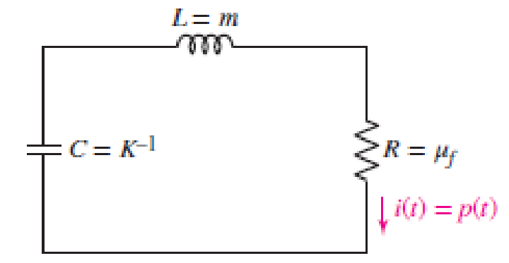
■ FIGURE 9.64
Want to see the full answer?
Check out a sample textbook solution
Chapter 9 Solutions
Loose Leaf for Engineering Circuit Analysis Format: Loose-leaf


- Model the dynamic behavior of this circuit for loop 1 (obtain differential equation) R₁ W 1 möm R₂ i, 2 លីនarrow_forwardFor function f(t) = 5 sin(2t) show analytically & graphically the function form subject to shift upwards by 5 units shift in time domain by 5 units left. Please answer in typing format and draw diagram on paper and cleanarrow_forwardFor the system described in problem 1, what is the steady-state error for the ramp input r(t) 10tu (t)? %3D Edit View Insert Format Tools Tablearrow_forward
- 18. A dc voltage E is applied across an RL circuit at t = 0. At what time after, is the voltage across the resistor equal to that across the inductor? A. 0.693 TC B. 0.673 TC C. 0.707 TC D. 0.779 TCarrow_forwardsolve for the dc quantities, VB(Q1), and VB(Q2)arrow_forwardLearning Goal: To analyze an RC circuit to determine the initial voltage across a capacitor, then to find the step response of the capacitor voltage, and finally to find other circuit quantities, such as current, voltage, power, or energy. The step response of an RC circuit is the response of the capacitor voltage to a sudden application of a DC source. When the switching occurs, the capacitor stores or releases energy. (Figure 1) Figure R₁ R₂ www R3 b R4 ,t=0 1 of 1 R6 R5 ww Part D Write an expression for the capacitor voltage, v(t), for t > 0. Express your answer as an algebraic expression in terms of Vs, Is, R3, R5, R6, C. ► View Available Hint(s) v(t) = Submit Part E p(t) = ΑΣΦ Submit vec Write an expression for the power dissipated in the resistor R6 for t > 0+. Express your answer as an algebraic expression in terms of VS, Is, R3, R5, R6, and C. ► View Available Hint(s) V ΑΣΦ ? ↓↑ vec V ? mWarrow_forward
- circuit theory I want the answer before 30 minutes, please. I want the answer as soon as possible, because I do not have time, and if I skip the specified time, I do not benefit from the answer.arrow_forwardProblem 2 Define the initial current , the final current Is, the time constant r, and the current i at 32 us. 0mll 12v The switch is closed at t-0.arrow_forwardQuestion 2 An electric circuit consists of a battery (voltage source) connected to a resistor and capacitor in series. The resulting ordinary differential equation for the voltage on the capacitor Vc(t) is as follows: We will use the values (b) Vin function dVc dt + - + C = 0.001 Vin 1 RC RC - R VR satisfies the ODE and the initial condition. 1 1000' Vo = 9 Here resistance R is in Ohms, time t is in seconds, capacitance C is in Farads, and voltage Vin is in Volts. Initially, the voltage on the capacitor is zero: Vc(0) = = 0. (a) Assume the resistance is constant: R Vc(t). = Vc Q Vc(t) = 9(1-e-10t) 100. Check by direct substitution that the Now assume that the resistor slowly degrades, so that its resistance increases with time: = R(t) = = 100 + 2t. R= Solve the ordinary differential equation for Vc(t) with this resistance, using either separation of variables, or the integrating factor method. Make sure to also include the initial condition.arrow_forward
- Question regarding a signals and systems course, u(t) is the unit-step function, and r(t) is the ramp function. Imagine x(t)= r(t-1)-r(t-2)+u(t-3)-u(t-4)-r(t-5)+r(t-6): a) Draw x(t) b) Draw 2x(t+2) c) Draw x(t+2) + x(t+3)arrow_forwardThe switch S is closed at t = 0. Which statements about the following RL circuit are true? (Assume a DC source and that the inductors have no resistance.) Circle all answers that apply. L L R (A) Immediately after the switch is closed, the source sees an equivalent resistance of R/2. (B) Immediately after the switch is closed, the source sees an equivalent resistance of 2R. (C) Immediately after the switch is closed, the source sees an equivalent resistance of 3R/2. (D) At t = infinity after the switch is closed, the source sees an equivalent resistance of R. (E) At t = infinity after the switch is closed, the source sees an equivalent resistance of 2R. (F) At t = infinity after the switch is closed, the source sees an equivalent resistance of 3R/2.arrow_forwardDetermine the time constant of the circuit when the switch is throwninto position 1.Find the mathematical expression for the voltage across the capacitorand the current after the switch is thrown into position 1.Determine the magnitude of the voltage vC and the current iC the instantthe switch is thrown into position 2 at t = 1 s.arrow_forward
 Introductory Circuit Analysis (13th Edition)Electrical EngineeringISBN:9780133923605Author:Robert L. BoylestadPublisher:PEARSON
 Delmar's Standard Textbook Of ElectricityElectrical EngineeringISBN:9781337900348Author:Stephen L. HermanPublisher:Cengage Learning
 Programmable Logic ControllersElectrical EngineeringISBN:9780073373843Author:Frank D. PetruzellaPublisher:McGraw-Hill Education
 Fundamentals of Electric CircuitsElectrical EngineeringISBN:9780078028229Author:Charles K Alexander, Matthew SadikuPublisher:McGraw-Hill Education
 Electric Circuits. (11th Edition)Electrical EngineeringISBN:9780134746968Author:James W. Nilsson, Susan RiedelPublisher:PEARSON
 Engineering ElectromagneticsElectrical EngineeringISBN:9780078028151Author:Hayt, William H. (william Hart), Jr, BUCK, John A.Publisher:Mcgraw-hill Education,