
Loose Leaf for Engineering Circuit Analysis Format: Loose-leaf
9th Edition
ISBN: 9781259989452
Author: Hayt
Publisher: Mcgraw Hill Publishers
expand_more
expand_more
format_list_bulleted
Concept explainers
Videos
Textbook Question
Chapter 9, Problem 67E
The capacitor in the circuit of Fig. 9.63 is set to I F. Determine vC(t) at (a) t = −1 s; (b) t = 0+; (c) t = 20 s.
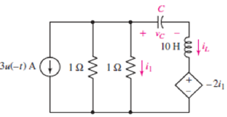
FIGURE 9.63
Expert Solution & Answer
Want to see the full answer?
Check out a sample textbook solution
Students have asked these similar questions
Problen the following:
A. The voltage across the capacitor at the t = 0.
B. The voltage across the capacitor for t > 0.
C. The voltage across the 32K resistor for t > 0.
Given RC circuit with a switch that moves from position A to B at time t =0 obtain
Obtain an equation for vc as labeled in the circuit of Fig. 9.48 valid for all
t > 0.
t = 0
2i
+ VC
100 Q
40 µF
9 V (*
30 Q
90 mH
FIGURE 9.48
9. The circuit is at steady state before the switch opens at time t = 0. The output of
this circuit is the voltage across the capacitor, v(t). Determine v(t) for t> 0.
t=0
60 ΚΩ
30 ΚΩ
ww
otá
www
6 V(+
5 μF
v(t) =
60 ΚΩ
+
v(1)
36 V (+
Chapter 9 Solutions
Loose Leaf for Engineering Circuit Analysis Format: Loose-leaf
Ch. 9.1 - A parallel RLC circuit contains a 100 2 resistor...Ch. 9.2 - After being open for a long time, the switch in...Ch. 9.2 - Prob. 3PCh. 9.2 - Prob. 4PCh. 9.3 - (a) Choose R1 in the circuit of Fig. 9.14 so that...Ch. 9.4 - Prob. 6PCh. 9.5 - Prob. 7PCh. 9.5 - Prob. 8PCh. 9.6 - Let is = 10u(t) 20u(t) A in Fig. 9.31. Find (a)...Ch. 9.6 - Let vs = 10 + 20u(t) V in the circuit of Fig....
Ch. 9.7 - Alter the capacitor value and voltage source in...Ch. 9 - For a certain source-free parallel RLC circuit, R...Ch. 9 - Element values of 10 mF and 2 nH are employed in...Ch. 9 - If a parallel RLC circuit is constructed from...Ch. 9 - Prob. 4ECh. 9 - You go to construct the circuit in Exercise 1,...Ch. 9 - A parallel RLC circuit has inductance 2 mH and...Ch. 9 - Prob. 7ECh. 9 - A parallel RLC circuit has R = 1 k, L = 50 mH. and...Ch. 9 - Prob. 9ECh. 9 - Prob. 10ECh. 9 - The current flowing through a 5 resistor in a...Ch. 9 - For the circuit of Fig.9.40, obtain an expression...Ch. 9 - Consider the circuit depicted in Fig. 9.40. (a)...Ch. 9 - With regard to the circuit represented in Fig....Ch. 9 - (a) Assuming the passive sign convention, obtain...Ch. 9 - With regard to the circuit presented in Fig. 9.42,...Ch. 9 - Obtain expressions for the current i(t) and...Ch. 9 - FIGURE 9.43 Replace the 14 resistor in the...Ch. 9 - Design a complete source-free parallel RLC circuit...Ch. 9 - For the circuit represented by Fig. 9.44, the two...Ch. 9 - Prob. 21ECh. 9 - Prob. 22ECh. 9 - A critically damped parallel RLC circuit is...Ch. 9 - A source-free parallel RLC circuit has an initial...Ch. 9 - A critically damped parallel RLC circuit is...Ch. 9 - For the circuit of Fig. 9.45, is(t) = 30u(t) mA....Ch. 9 - Prob. 27ECh. 9 - The circuit of Fig. 9.44 is rebuilt such that the...Ch. 9 - Prob. 29ECh. 9 - Prob. 30ECh. 9 - The source-free circuit depicted in Fig. 9.1 is...Ch. 9 - (a) Graph the current i for the circuit described...Ch. 9 - Analyze the circuit described in Exercise 31 to...Ch. 9 - A source-free parallel RLC circuit has capacitance...Ch. 9 - Prob. 35ECh. 9 - Obtain an expression for vL(t), t 0, for the...Ch. 9 - For the circuit of Fig. 9.47, determine (a) the...Ch. 9 - (a) Design a parallel RLC circuit that provides a...Ch. 9 - The circuit depicted in Fig. 9.48 is just barely...Ch. 9 - When constructing the circuit of Fig. 9.48, you...Ch. 9 - The circuit of Fig. 9.22a is constructed with a...Ch. 9 - Prob. 42ECh. 9 - Prob. 43ECh. 9 - The simple three-element series RLC circuit of...Ch. 9 - Prob. 45ECh. 9 - Prob. 46ECh. 9 - Prob. 47ECh. 9 - With reference to the series RLC circuit of Fig....Ch. 9 - Obtain an expression for i1 as labeled in Fig....Ch. 9 - The circuit in Fig. 9.52 has the switch in...Ch. 9 - For the circuit in Fig. 9.52, determine the value...Ch. 9 - In the series circuit of Fig. 9.53, set R = 1 ....Ch. 9 - Evaluate the derivative of each current and...Ch. 9 - Consider the circuit depicted in Fig. 9.55. If...Ch. 9 - Prob. 55ECh. 9 - In the circuit shown in Fig. 9.56, (a) obtain an...Ch. 9 - Prob. 57ECh. 9 - For the circuit represented in Fig. 9.57, (a)...Ch. 9 - FIGURE 9.57 Replace the 1 resistor in Fig. 9.57...Ch. 9 - A circuit has an inductive load of 2 H, a...Ch. 9 - (a) Adjust the value of the 3 resistor in the...Ch. 9 - Determine expressions for vC(t) and iL(t) in Fig....Ch. 9 - The capacitor in the LC circuit in Fig. 9.60 has...Ch. 9 - Suppose that the switch in the circuit in Fig....Ch. 9 - The capacitor in the circuit of Fig. 9.63 is set...Ch. 9 - The physical behavior of automotive suspension...Ch. 9 - A lossless LC circuit can be used to provide...
Knowledge Booster


Learn more about
Need a deep-dive on the concept behind this application? Look no further. Learn more about this topic, electrical-engineering and related others by exploring similar questions and additional content below.Similar questions
- Find the Thevenin equivalent of the 2-terminal a – b in sinusoidal steady state. e(t)=2 sin(2t), C=1F, L=1H, R=½Q o a e(t) obarrow_forward37. For the circuit of Fig. 9.47, determine (a) the first time t> 0 when v(t) = 0. 2 V 592 592 ww t=0 + I 2 mF m elle 5u(-1) V + 20 mH 292arrow_forwardIn the circuit depicted below, determine the voltage across the capacitor for t > 0. Your answer will be a function of t, using impulsive functions to represent discontinuities. 50 5 A 0.01 F 0.2 H 25 u(t) V Edit View Insert Format Tools Table 12pt v Paragraph v BIUA ...arrow_forward
- (a) A system consists of two components that can be presented by the respective h₁ (t) = 3000e-2⁰tu(t) and h₂(t) = te-1⁰tu(t) as illustrated in Figure Q.1(a). The input voltage for the system is: Vin (t) Vin (t) = cos(t) + 2 cos(10t) + 10 cos (1000t) V h(t) h₁ (t) Figure Q.1(a) h₂ (t) → Vout (t) (i) Determine the system transfer function, H(s) (ii) Sketch the magnitude bode plot for the system transfer function in (i), H(s) (iii) Determine the magnitude of the output voltages, Vout (t) at w = 1rad/s and w = 10rad/sarrow_forwardExpress the following signals in terms of singularity functions: vj(1) A 1 -1 -1 a. Singularity Function vz(t) 4 2 0 2 4 t b. Singularity Functionarrow_forwardProblem: Determine the current through the inductor, iL(t) in the figure of a circuit diagram below. No energy has been stored in the circuit prior to t = 0 seconds. The applied current input consists of a 12A step input applied at t = 0. Find and solve for the value of iL(t) = τarrow_forward
- Determine the current through the inductor, iL(t), in the circuit below. No energy is stored in the circuit prior to t = 0 seconds. The applied current input consists of a 12 A step input applied at t = 0. Solve also for iL(t) = tauarrow_forwardWith reference to the figure below, sketch the inductor voltage, v, as a function of time, 0arrow_forwardConsider the following circuit. In the circuit, A=3, R1= 4N, R2= 4N,and a =5 R2 2F R1 aic(t) A - Au(t) (1 velt) -tic(t) a) Determine the capacitor voltage at t=0 K and b) The expression for V(s) is- s+p Determine K c) Determine the value of v.(t) at t=2 s d) What is the value of the time constant of the circuit for t>0? +arrow_forwardThe capacitor voltage in the circuit shown in Figure is given by v (t) = 12 - 10e-2t V for t 0 Determine i(t) for t > 0. i(t) in Amperes for t>0 is F+Ge 2t Find F and G. i(t) 4Ω 6Ω 1) 2 A + v(t) F 20 5:03 PM 66°F Mostly cloudy 4/3/2022 Oarrow_forwardThe input to the circuit shown in the figure below is the voltage V(t) = 4e-20 t V for t > 0 The output is the current i(t) = -1.2e-20t V for t > 0 The initial inductor current is iL(0) = -3.5 A. Find the values of inductance L and resistance R. Please answer in typing format solution pleasearrow_forwardThe inductor current in the circuit is given by 6(1 – e-8t) A (t > 0). (a) Determine the current of the 80 resistor for t > 0. Hint: you need v20: (b) In the limit t→o, does the mathematical solution for igo agree with the circuit at t = 0? Explain your reasoning. Answer: 1.2e-8t A 12V 30.2Harrow_forwardarrow_back_iosSEE MORE QUESTIONSarrow_forward_ios
Recommended textbooks for you
 Introductory Circuit Analysis (13th Edition)Electrical EngineeringISBN:9780133923605Author:Robert L. BoylestadPublisher:PEARSON
 Delmar's Standard Textbook Of ElectricityElectrical EngineeringISBN:9781337900348Author:Stephen L. HermanPublisher:Cengage Learning
 Programmable Logic ControllersElectrical EngineeringISBN:9780073373843Author:Frank D. PetruzellaPublisher:McGraw-Hill Education
 Fundamentals of Electric CircuitsElectrical EngineeringISBN:9780078028229Author:Charles K Alexander, Matthew SadikuPublisher:McGraw-Hill Education
 Electric Circuits. (11th Edition)Electrical EngineeringISBN:9780134746968Author:James W. Nilsson, Susan RiedelPublisher:PEARSON
 Engineering ElectromagneticsElectrical EngineeringISBN:9780078028151Author:Hayt, William H. (william Hart), Jr, BUCK, John A.Publisher:Mcgraw-hill Education,
Introductory Circuit Analysis (13th Edition)
Electrical Engineering
ISBN:9780133923605
Author:Robert L. Boylestad
Publisher:PEARSON
Delmar's Standard Textbook Of Electricity
Electrical Engineering
ISBN:9781337900348
Author:Stephen L. Herman
Publisher:Cengage Learning
Programmable Logic Controllers
Electrical Engineering
ISBN:9780073373843
Author:Frank D. Petruzella
Publisher:McGraw-Hill Education
Fundamentals of Electric Circuits
Electrical Engineering
ISBN:9780078028229
Author:Charles K Alexander, Matthew Sadiku
Publisher:McGraw-Hill Education
Electric Circuits. (11th Edition)
Electrical Engineering
ISBN:9780134746968
Author:James W. Nilsson, Susan Riedel
Publisher:PEARSON
Engineering Electromagnetics
Electrical Engineering
ISBN:9780078028151
Author:Hayt, William H. (william Hart), Jr, BUCK, John A.
Publisher:Mcgraw-hill Education,
ENA 9.2(1)(En)(Alex) Sinusoids & Phasors - Explanation with Example 9.1 ,9.2 & PP 9.2; Author: Electrical Engineering Academy;https://www.youtube.com/watch?v=vX_LLNl-ZpU;License: Standard YouTube License, CC-BY
Electrical Engineering: Ch 10 Alternating Voltages & Phasors (8 of 82) What is a Phasor?; Author: Michel van Biezen;https://www.youtube.com/watch?v=2I1tF3ixNg0;License: Standard Youtube License