
Loose Leaf for Engineering Circuit Analysis Format: Loose-leaf
9th Edition
ISBN: 9781259989452
Author: Hayt
Publisher: Mcgraw Hill Publishers
expand_more
expand_more
format_list_bulleted
Videos
Textbook Question
Chapter 9.3, Problem 5P
(a) Choose R1 in the circuit of Fig. 9.14 so that the response after t = 0 will be critically damped. (b) Now select R2 to obtain v(0) = 100 V. (c) Find v(t) at t = 1 ms.
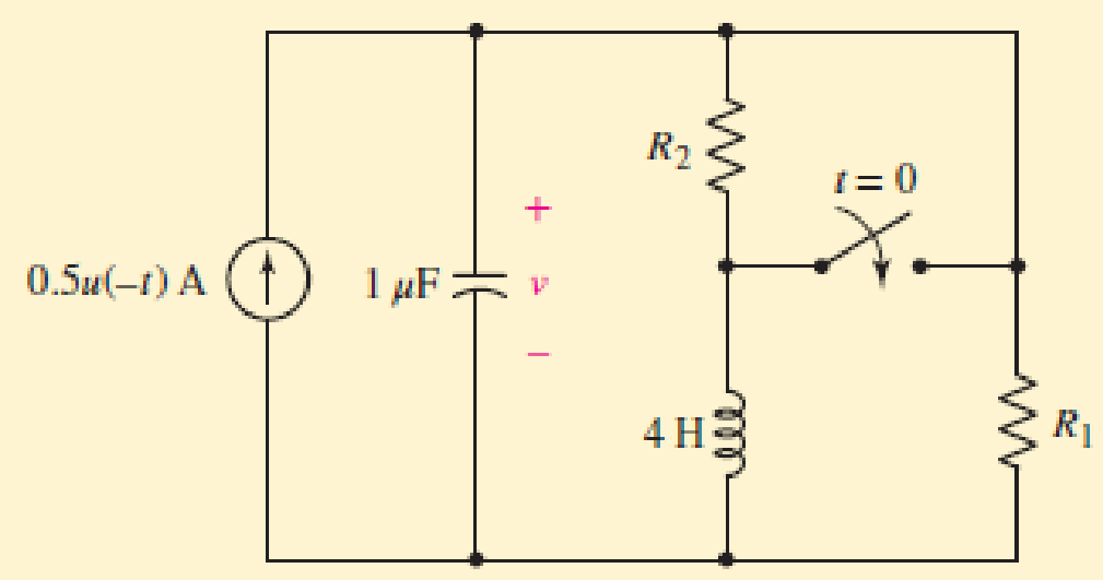
FIGURE 9.14
Expert Solution & Answer
Want to see the full answer?
Check out a sample textbook solution
Students have asked these similar questions
9. At t = 0, the switch in the circuit below opens. Prior to t = 0 the circuit is in steady state.
Find iL(t) for all times, if L = 1 H. Sketch iL(t) vs. t.
0.2 F
t = 0
20
IL
5 A (
10. Repeat problem 9 if L = 0.2 H.
Q1: For the servo system shown in figure (1). Find the values of a, b, and K, to obtain
response of damping ratio (= 0.2) and natural frequency (0-6)
the
required
R(S) +
Figure (1)
K
s+a
s+b
compensator
2
2
S
Plant
C(s)
7) What is the damping ratio of the closed loop system shown in the figure?
a) 0
R(s)
b) 1
5
(s+1)(s+3)
C(s)
Chapter 9 Solutions
Loose Leaf for Engineering Circuit Analysis Format: Loose-leaf
Ch. 9.1 - A parallel RLC circuit contains a 100 2 resistor...Ch. 9.2 - After being open for a long time, the switch in...Ch. 9.2 - Prob. 3PCh. 9.2 - Prob. 4PCh. 9.3 - (a) Choose R1 in the circuit of Fig. 9.14 so that...Ch. 9.4 - Prob. 6PCh. 9.5 - Prob. 7PCh. 9.5 - Prob. 8PCh. 9.6 - Let is = 10u(t) 20u(t) A in Fig. 9.31. Find (a)...Ch. 9.6 - Let vs = 10 + 20u(t) V in the circuit of Fig....
Ch. 9.7 - Alter the capacitor value and voltage source in...Ch. 9 - For a certain source-free parallel RLC circuit, R...Ch. 9 - Element values of 10 mF and 2 nH are employed in...Ch. 9 - If a parallel RLC circuit is constructed from...Ch. 9 - Prob. 4ECh. 9 - You go to construct the circuit in Exercise 1,...Ch. 9 - A parallel RLC circuit has inductance 2 mH and...Ch. 9 - Prob. 7ECh. 9 - A parallel RLC circuit has R = 1 k, L = 50 mH. and...Ch. 9 - Prob. 9ECh. 9 - Prob. 10ECh. 9 - The current flowing through a 5 resistor in a...Ch. 9 - For the circuit of Fig.9.40, obtain an expression...Ch. 9 - Consider the circuit depicted in Fig. 9.40. (a)...Ch. 9 - With regard to the circuit represented in Fig....Ch. 9 - (a) Assuming the passive sign convention, obtain...Ch. 9 - With regard to the circuit presented in Fig. 9.42,...Ch. 9 - Obtain expressions for the current i(t) and...Ch. 9 - FIGURE 9.43 Replace the 14 resistor in the...Ch. 9 - Design a complete source-free parallel RLC circuit...Ch. 9 - For the circuit represented by Fig. 9.44, the two...Ch. 9 - Prob. 21ECh. 9 - Prob. 22ECh. 9 - A critically damped parallel RLC circuit is...Ch. 9 - A source-free parallel RLC circuit has an initial...Ch. 9 - A critically damped parallel RLC circuit is...Ch. 9 - For the circuit of Fig. 9.45, is(t) = 30u(t) mA....Ch. 9 - Prob. 27ECh. 9 - The circuit of Fig. 9.44 is rebuilt such that the...Ch. 9 - Prob. 29ECh. 9 - Prob. 30ECh. 9 - The source-free circuit depicted in Fig. 9.1 is...Ch. 9 - (a) Graph the current i for the circuit described...Ch. 9 - Analyze the circuit described in Exercise 31 to...Ch. 9 - A source-free parallel RLC circuit has capacitance...Ch. 9 - Prob. 35ECh. 9 - Obtain an expression for vL(t), t 0, for the...Ch. 9 - For the circuit of Fig. 9.47, determine (a) the...Ch. 9 - (a) Design a parallel RLC circuit that provides a...Ch. 9 - The circuit depicted in Fig. 9.48 is just barely...Ch. 9 - When constructing the circuit of Fig. 9.48, you...Ch. 9 - The circuit of Fig. 9.22a is constructed with a...Ch. 9 - Prob. 42ECh. 9 - Prob. 43ECh. 9 - The simple three-element series RLC circuit of...Ch. 9 - Prob. 45ECh. 9 - Prob. 46ECh. 9 - Prob. 47ECh. 9 - With reference to the series RLC circuit of Fig....Ch. 9 - Obtain an expression for i1 as labeled in Fig....Ch. 9 - The circuit in Fig. 9.52 has the switch in...Ch. 9 - For the circuit in Fig. 9.52, determine the value...Ch. 9 - In the series circuit of Fig. 9.53, set R = 1 ....Ch. 9 - Evaluate the derivative of each current and...Ch. 9 - Consider the circuit depicted in Fig. 9.55. If...Ch. 9 - Prob. 55ECh. 9 - In the circuit shown in Fig. 9.56, (a) obtain an...Ch. 9 - Prob. 57ECh. 9 - For the circuit represented in Fig. 9.57, (a)...Ch. 9 - FIGURE 9.57 Replace the 1 resistor in Fig. 9.57...Ch. 9 - A circuit has an inductive load of 2 H, a...Ch. 9 - (a) Adjust the value of the 3 resistor in the...Ch. 9 - Determine expressions for vC(t) and iL(t) in Fig....Ch. 9 - The capacitor in the LC circuit in Fig. 9.60 has...Ch. 9 - Suppose that the switch in the circuit in Fig....Ch. 9 - The capacitor in the circuit of Fig. 9.63 is set...Ch. 9 - The physical behavior of automotive suspension...Ch. 9 - A lossless LC circuit can be used to provide...
Knowledge Booster


Learn more about
Need a deep-dive on the concept behind this application? Look no further. Learn more about this topic, electrical-engineering and related others by exploring similar questions and additional content below.Similar questions
- The' Transfer Fcn'block can be extracted from 'Commonly Used Blocks' library. If the dumping ratio is between 0 and 1, the system poles are complex conjugates. A step input can be described as a change in the input from zero to a infinite value at time t = 0. If the damping factor is zero, the unit-step response is a Purely sinusoidal. Manual controlarrow_forwardFor the circuit shown in figure 1, assume that the switch was closed for a long time before t = 0. The switch changes its position at t = 0. Now, answer the following: P1. Determine the initial conditions for the capacitor and the inductor (That is the voltage of the capacitor and the current through the inductor before t = 0) [Hint: Mesh analysis might be helpful] P2. Convert the circuit in s-domain for t 20 P3. Then calculate the current through the capacitor i(s) P4. Take the partial fraction of i(s) [if necessary], and then take the inverse Laplace transform of i(s) to get the current i(t) 6Ω 6Ω 6Ω i(t) t = 0 2H :0.5F 12V 4V Figure 1: Circuit for question 2 +, llarrow_forwardThe switch has been closed for a long time in this DC circuit. The switch opens at t = 0s. Is the system over, under or critically damped (circle one)? Show your work. For t≥ 0, ve(t)= V for t≥ 0.arrow_forward
- 1. For the following circuit, switch is closed at t=0. a. Write a differential equation in i(t). b. Find a and wo. c. Find the characteristic equation and the roots of the characteristic equation. d. Find the final value of current i(t) through the inductor. e. Find current i(t) through the inductor for t> 0 and sketch i(t). f. Find voltage v(t) for t≥ 0 and sketch v(t). PS Solution Switch S Vs 20V R1 ΣΚΩ www R2 2k2 v(t) V=4V I 50 nF i(t) 40mH lo=5mAarrow_forwardCalculate V1 and v2 for t > 0, if the circuit is in steady stateat t = 0-. how to get the written answer to the template under the circuit?arrow_forwardNatural Response of RLC Circuita. charge in capacitor at steady state b. di/dt (in A/s) at t=0+(The previous answer which were 0.001 and -31.25 were incorrect. I do not know what were the miscalculations, please do NOT provide those as answers anymore. Thanks)arrow_forward
- The switches in the circuit shown below have been open (left switch) and closed (right switch) for a longtime. At time equal to zero this switches change as indicated in figure. a) Find the numerical expressionsfor iL(t) and vo(t) for t ≥ 0. b) Find the numerical values of vL(0+) and vo(0+).arrow_forwardsolve for the dc quantities, VB(Q1), and VB(Q2)arrow_forwardFor the circuit in the attached figure knowing that t0 = 0 s and that iL(t0) = i0. Find the mathematical expression for ix(t) on the interval t1 t < t2. Determine your answer in amps (A).arrow_forward
- The Source-Free Series RLC Circuit The circuit of Fig. 9.21a is constructed with a 160 mF capacitor and a 250 mH inductor. Determine the value of R needed to obtain (a) a critically damped response; (b) a "just barely" underdamped response. (c) Compare your answers to parts (a) and (b) if the circuit was a parallel RLC circuit. R VC + (a) L + VL + V (b) FIGURE 9.21 (a) The series RLC circuit which is the dual of (b) a parallel RLC circuit. Element values are, of course, not identical in the two circuits.arrow_forwardIn the figure below, the switch will open at t=0. Using step-by-step method, find Vo(t) for t>0. Also, draw Vo(t) on a rough scale clearly indicating its value at t=0 and the direction of exponential curve. t-o 2kN 2kN. t=0 2kN 2kN 10V 10uF 2kN Vo(t) O +arrow_forward.With regard to the circuit of Fig. 9.55, obtain an expression for vCvalid for t≥0if is(t) =3u(−t) +5u(t) mAarrow_forward
arrow_back_ios
SEE MORE QUESTIONS
arrow_forward_ios
Recommended textbooks for you
 Introductory Circuit Analysis (13th Edition)Electrical EngineeringISBN:9780133923605Author:Robert L. BoylestadPublisher:PEARSON
 Delmar's Standard Textbook Of ElectricityElectrical EngineeringISBN:9781337900348Author:Stephen L. HermanPublisher:Cengage Learning
 Programmable Logic ControllersElectrical EngineeringISBN:9780073373843Author:Frank D. PetruzellaPublisher:McGraw-Hill Education
 Fundamentals of Electric CircuitsElectrical EngineeringISBN:9780078028229Author:Charles K Alexander, Matthew SadikuPublisher:McGraw-Hill Education
 Electric Circuits. (11th Edition)Electrical EngineeringISBN:9780134746968Author:James W. Nilsson, Susan RiedelPublisher:PEARSON
 Engineering ElectromagneticsElectrical EngineeringISBN:9780078028151Author:Hayt, William H. (william Hart), Jr, BUCK, John A.Publisher:Mcgraw-hill Education,
Introductory Circuit Analysis (13th Edition)
Electrical Engineering
ISBN:9780133923605
Author:Robert L. Boylestad
Publisher:PEARSON
Delmar's Standard Textbook Of Electricity
Electrical Engineering
ISBN:9781337900348
Author:Stephen L. Herman
Publisher:Cengage Learning
Programmable Logic Controllers
Electrical Engineering
ISBN:9780073373843
Author:Frank D. Petruzella
Publisher:McGraw-Hill Education
Fundamentals of Electric Circuits
Electrical Engineering
ISBN:9780078028229
Author:Charles K Alexander, Matthew Sadiku
Publisher:McGraw-Hill Education
Electric Circuits. (11th Edition)
Electrical Engineering
ISBN:9780134746968
Author:James W. Nilsson, Susan Riedel
Publisher:PEARSON
Engineering Electromagnetics
Electrical Engineering
ISBN:9780078028151
Author:Hayt, William H. (william Hart), Jr, BUCK, John A.
Publisher:Mcgraw-hill Education,
Random Variables and Probability Distributions; Author: Dr Nic's Maths and Stats;https://www.youtube.com/watch?v=lHCpYeFvTs0;License: Standard Youtube License