
Loose Leaf for Engineering Circuit Analysis Format: Loose-leaf
9th Edition
ISBN: 9781259989452
Author: Hayt
Publisher: Mcgraw Hill Publishers
expand_more
expand_more
format_list_bulleted
Concept explainers
Videos
Textbook Question
Chapter 8, Problem 24E
The switch in the circuit of Fig. 8.58 has been closed a ridiculously long time before suddenly being thrown open at t = 0. (a) Obtain expressions for iL and v in the circuit of Fig. 8.58, which are valid for all t ≥ 0. (b) Calculate iL(t) and v(t) at the instant just prior to the switch opening, at the instant just after the switch opening, and at t = 470 μs.
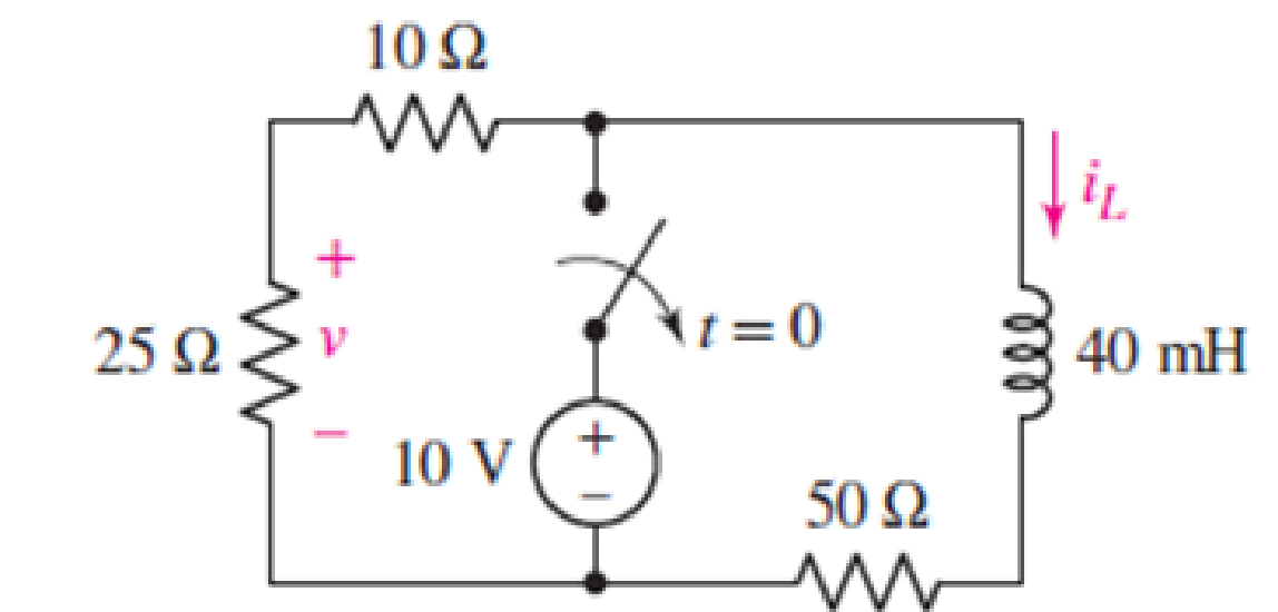
Figure 8.58
Expert Solution & Answer
Want to see the full answer?
Check out a sample textbook solution
Students have asked these similar questions
8.5 From the circuit in the figure, if the switch was initially connected with a resistance of 2Ω for a long time and opened as shown at time t = 0, find i0(t) and v0(t) when t > 0
Obtain an expression for i1 as indicated in Fig. 8.85 that is valid for all values
of t.
8H
i(t)
Q.39: The switch in the circuit shown in figure
beside has been closed for a long time, then
opened
expression for the current through the
inductor i(t).
12A
U8
162
at
t=0.
Find
the
numerical
U8
Chapter 8 Solutions
Loose Leaf for Engineering Circuit Analysis Format: Loose-leaf
Ch. 8.1 - For the circuit in Fig. 8.2, what value of...Ch. 8.1 - Noting carefully how the circuit changes once the...Ch. 8.2 - In a source-free series RC circuit, find the...Ch. 8.3 - Prob. 4PCh. 8.3 - Prob. 5PCh. 8.4 - Prob. 6PCh. 8.4 - Prob. 7PCh. 8.4 - Prob. 8PCh. 8.5 - Evaluate each of the following at t = 0.8: (a)...Ch. 8.6 - For the circuit of Fig. 8.37, find vc(t) at t...
Ch. 8.7 - Prob. 11PCh. 8.7 - The voltage source 60 40u(t) V is in series with...Ch. 8.7 - Prob. 13PCh. 8.8 - Prob. 14PCh. 8.8 - Prob. 15PCh. 8 - A source-free RC circuit has R = 4 k and C = 22 F,...Ch. 8 - A source-free RC circuit has v(0) = 12 V and R =...Ch. 8 - The resistor in the circuit of Fig. 8.51 has been...Ch. 8 - Prob. 4ECh. 8 - Prob. 5ECh. 8 - Prob. 6ECh. 8 - Prob. 7ECh. 8 - Prob. 8ECh. 8 - Prob. 9ECh. 8 - The switch in Fig. 8.56 has been closed for a long...Ch. 8 - For the circuit in Fig. 8.56, find (a) the total...Ch. 8 - Design a capacitor-based circuit that can achieve...Ch. 8 - (a) Graph the function f (t) = 10e2t over the...Ch. 8 - The current i(t) flowing through a 1 k resistor is...Ch. 8 - Radiocarbon dating has a similar exponential time...Ch. 8 - For the circuit of Fig. 8.4, compute the time...Ch. 8 - Design a circuit which will produce a current of 1...Ch. 8 - Prob. 18ECh. 8 - Prob. 19ECh. 8 - Referring to the circuit shown in Fig. 8.11,...Ch. 8 - Prob. 21ECh. 8 - With the assumption that the switch in the circuit...Ch. 8 - The switch in Fig. 8.57 has been closed since...Ch. 8 - The switch in the circuit of Fig. 8.58 has been...Ch. 8 - Assuming the switch initially has been open for a...Ch. 8 - (a) Obtain an expression for v(t), the voltage...Ch. 8 - For the circuit of Fig. 8.61, determine ix, iL,...Ch. 8 - Prob. 28ECh. 8 - Prob. 29ECh. 8 - Prob. 30ECh. 8 - Prob. 31ECh. 8 - (a) Obtain an expression for vx as labeled in the...Ch. 8 - Prob. 33ECh. 8 - Prob. 34ECh. 8 - Prob. 35ECh. 8 - Prob. 36ECh. 8 - Prob. 37ECh. 8 - The switch in Fig. 8.70 is moved from A to B at t...Ch. 8 - Prob. 39ECh. 8 - Prob. 40ECh. 8 - Evaluate the following functions at t = 1, 0, and...Ch. 8 - Prob. 42ECh. 8 - Prob. 43ECh. 8 - Prob. 44ECh. 8 - You can use MATLAB to represent the unit-step...Ch. 8 - With reference to the circuit depicted in Fig....Ch. 8 - For the circuit given in Fig. 8.75, (a) determine...Ch. 8 - Prob. 48ECh. 8 - Prob. 49ECh. 8 - You build a portable solar charging circuit...Ch. 8 - The switch in the circuit of Fig. 8.78 has been...Ch. 8 - The switch in the circuit of Fig. 8.78 has been...Ch. 8 - Prob. 53ECh. 8 - Prob. 54ECh. 8 - Prob. 55ECh. 8 - For the circuit represented in Fig. 8.82, (a)...Ch. 8 - Prob. 58ECh. 8 - Prob. 59ECh. 8 - For the circuit given in Fig. 8.85, (a) determine...Ch. 8 - The circuit depicted in Fig. 8.86 contains two...Ch. 8 - Prob. 62ECh. 8 - Prob. 63ECh. 8 - A series RL circuit has a voltage that steps from...Ch. 8 - For the two-source circuit of Fig. 8.89, note that...Ch. 8 - (a) Obtain an expression for iL as labeled in Fig....Ch. 8 - Obtain an expression for i(t) as labeled in the...Ch. 8 - Obtain an expression for i1 as indicated in Fig....Ch. 8 - Plot the current i(t) in Fig. 8.93 if (a) R = 10 ;...Ch. 8 - A dc motor can be modeled as a series RL circuit...Ch. 8 - Prob. 71ECh. 8 - Prob. 72ECh. 8 - A series RC sequentially switched circuit has R =...Ch. 8 - Refer to the circuit of Fig. 8.95, which contains...Ch. 8 - In the circuit of Fig. 8.95, a 3 mF capacitor is...Ch. 8 - Prob. 78E
Knowledge Booster


Learn more about
Need a deep-dive on the concept behind this application? Look no further. Learn more about this topic, electrical-engineering and related others by exploring similar questions and additional content below.Similar questions
- 8.3.3 For the RLC circuit shown in the image below, if R1 = 7 2 and R2 = 7 2, C = 0.36 F, and the power source Vs = 18 V, determine the initial value VR (0T). %3D Please pay attention: the numbers may change since they are randomized. Your answer must include 2 places after the decimal point, and proper SI unit. R2 Vc + VR R1 2u(t) A Vs Your Answer: Answer units 118 llarrow_forward8.23 At t=0 s, a 100-V source is switched in series with a 1-k resistor and an uncharged 2-µF capacitor. What are (a) the initial capacitor voltage, (b) the initial current, (c) the initial rate of capacitor voltage increase, and (d) the time required for the capacitor voltage to reach its maximum value?arrow_forwardFigure 8 showsa resistor inductor capacitor (RLC) circuit. The input to the system is the voltage v(t) and the output of the circuit is the current iz (t). 8 R, i(t) iz(t) v(t) Ve(t) R2 Figure 8 a) Determine differential equations containing i, (t), iz (t) and v. (t) for the appropriate meshes and nodes. b) Assuming zero initial conditions i) derive Laplace transformations of the differential equations found in a) ii) determine the transfer function G(s) = I2(s) VIs where l2(s) = L{i2 (t}} and V(s) = L{v(t}.arrow_forward
- Consider the given circuit. The switch has been closed for a very long time before opening at t=0s. Determine the expression for Io(t) for t≥0 (in ms) and the expression for the inductor voltage for t≥0.arrow_forward9. The circuit is at steady state before the switch opens at time t = 0. The output of this circuit is the voltage across the capacitor, v(t). Determine v(t) for t> 0. t=0 60 ΚΩ 30 ΚΩ ww otá www 6 V(+ 5 μF v(t) = 60 ΚΩ + v(1) 36 V (+arrow_forward8.4 Step-Response Series RLC Circuits (3) Example 4 Having been in position for a long time, the switch in the circuit below is moved to position b at t = 0. Find v(t) and vR(t) for t > 0. 2.5 H 10Ω a ww- 12 V 22 10 V • Please refer to lecture or textbook for more detail elaboration. Answer: v(t) = {10 + [(-2cos3.464t – 1.1547sin3.464t)e-2t]} V VR(t)= [2.31sin3.464t]e-2t V 15 -19 wwarrow_forward
- For the network shown below, the switch is closed on to position 1 when t = 0 and then moved to position 2 when t = 20 ms. Determine the voltage across the capacitor when t = 30 ms. Also plot the response of this circuit from time, t = 0 to t = 40 ms.arrow_forward8.3.1 For the RLC circuit shown in the image below, if R1 = 3 2 and R2 = 7 2, C = 0.44 F, and the power source Vs = 7 V, determine the initial value iL (0* ). Please pay attention: the numbers may change since they are randomized. Your answer must include 2 places after the decimal point, and proper SI unit. R2 + 2u(t) A R Vs Your Answer: Answer units 118 llarrow_forward8. A series RC circuit (Fig. 1 below) with one resistor (R=500 M) and one capacitor (C=0.5 µF) is connected to an AC voltage supply which supplies a voltage v=100 sin(1000t+309) (from t=0 to t=∞). The initial charge on the capacitor is Qo = 25 µC and the initial voltage on the capacitor is in the same sense as the AC voltage supply. Obtain the current for t > 0. Qo Figure 1 500 D 0.5 μF 100 V 10 Ω 250 0.01 H Figure 2 iz 250arrow_forward
- 2. For the following circuit, a. find a. b. find wo. c. write a differential equation in i(t). d. find the characteristic equation. e. find the roots of the characteristic equation. f. find the final value of current i(t) through the inductor. g. find current i(t) through the inductor for t≥ 0 and plot i(t). h. find voltage v(t) for t≥ 0 and plot v(t). 15 mA R 1 k lo-5 mA 100 L 40 mH v(t) - с 50 nF V-2Varrow_forwardLet the first order circuit be shown in the following figure:The switch shown is known to change itsstate from open to closed at time t = 0 and that,once this change has occurred, the circuit reaches thesteady state at approximately 4.5 μs.a) Show that the voltage, v (t), satisfies the following first-order differential equation:arrow_forward8.3.1 For the RLC circuit shown in the image below, if R₁ = 6 and R₂ = 1, C = 0.32 F, and the power source Vs = 17 V, determine the initial value i 1 (0+). Please pay attention: the numbers may change since they are randomized. Your answer must include 2 places after the decimal point, and proper Sl unit. + VR www R₁ 2u(t) A + VC C (+) Vs R₂ IL Harrow_forward
arrow_back_ios
SEE MORE QUESTIONS
arrow_forward_ios
Recommended textbooks for you
 Introductory Circuit Analysis (13th Edition)Electrical EngineeringISBN:9780133923605Author:Robert L. BoylestadPublisher:PEARSON
 Delmar's Standard Textbook Of ElectricityElectrical EngineeringISBN:9781337900348Author:Stephen L. HermanPublisher:Cengage Learning
 Programmable Logic ControllersElectrical EngineeringISBN:9780073373843Author:Frank D. PetruzellaPublisher:McGraw-Hill Education
 Fundamentals of Electric CircuitsElectrical EngineeringISBN:9780078028229Author:Charles K Alexander, Matthew SadikuPublisher:McGraw-Hill Education
 Electric Circuits. (11th Edition)Electrical EngineeringISBN:9780134746968Author:James W. Nilsson, Susan RiedelPublisher:PEARSON
 Engineering ElectromagneticsElectrical EngineeringISBN:9780078028151Author:Hayt, William H. (william Hart), Jr, BUCK, John A.Publisher:Mcgraw-hill Education,
Introductory Circuit Analysis (13th Edition)
Electrical Engineering
ISBN:9780133923605
Author:Robert L. Boylestad
Publisher:PEARSON
Delmar's Standard Textbook Of Electricity
Electrical Engineering
ISBN:9781337900348
Author:Stephen L. Herman
Publisher:Cengage Learning
Programmable Logic Controllers
Electrical Engineering
ISBN:9780073373843
Author:Frank D. Petruzella
Publisher:McGraw-Hill Education
Fundamentals of Electric Circuits
Electrical Engineering
ISBN:9780078028229
Author:Charles K Alexander, Matthew Sadiku
Publisher:McGraw-Hill Education
Electric Circuits. (11th Edition)
Electrical Engineering
ISBN:9780134746968
Author:James W. Nilsson, Susan Riedel
Publisher:PEARSON
Engineering Electromagnetics
Electrical Engineering
ISBN:9780078028151
Author:Hayt, William H. (william Hart), Jr, BUCK, John A.
Publisher:Mcgraw-hill Education,
ENA 9.2(1)(En)(Alex) Sinusoids & Phasors - Explanation with Example 9.1 ,9.2 & PP 9.2; Author: Electrical Engineering Academy;https://www.youtube.com/watch?v=vX_LLNl-ZpU;License: Standard YouTube License, CC-BY
Electrical Engineering: Ch 10 Alternating Voltages & Phasors (8 of 82) What is a Phasor?; Author: Michel van Biezen;https://www.youtube.com/watch?v=2I1tF3ixNg0;License: Standard Youtube License