
Loose Leaf for Engineering Circuit Analysis Format: Loose-leaf
9th Edition
ISBN: 9781259989452
Author: Hayt
Publisher: Mcgraw Hill Publishers
expand_more
expand_more
format_list_bulleted
Concept explainers
Videos
Textbook Question
Chapter 8, Problem 47E
For the circuit given in Fig. 8.75, (a) determine vC(0−), vC(0+), iC(0−), and iC(0+); (b) calculate vC(20 ms) and iC(20 ms). (c) Verify your answer to part (b) with an appropriate SPICE simulation.
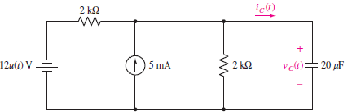
■ FIGURE 8.75
Expert Solution & Answer
Want to see the full answer?
Check out a sample textbook solution
Students have asked these similar questions
30
45
N 50 E
A
B
D
N
45
30
N 50 E
2.
100 m
(a)
Figure 8.44
N 40W
N 40 W
8. The PMOS in the image below, is specified to have Vth = -1V and kp = 0.4/V 2. The ideal current
source has 1 = 0.2mA. Find the voltage Vx.
10V
5ΚΩ
↓
Picture (1) we can see the circuit where L=4mH, C=2uF and Vs is given in picture (2). The question asks the value of İc at t=8ms.
Note: The time (t) given in the graph is in mili seconds (ms)
TIA
Chapter 8 Solutions
Loose Leaf for Engineering Circuit Analysis Format: Loose-leaf
Ch. 8.1 - For the circuit in Fig. 8.2, what value of...Ch. 8.1 - Noting carefully how the circuit changes once the...Ch. 8.2 - In a source-free series RC circuit, find the...Ch. 8.3 - Prob. 4PCh. 8.3 - Prob. 5PCh. 8.4 - Prob. 6PCh. 8.4 - Prob. 7PCh. 8.4 - Prob. 8PCh. 8.5 - Evaluate each of the following at t = 0.8: (a)...Ch. 8.6 - For the circuit of Fig. 8.37, find vc(t) at t...
Ch. 8.7 - Prob. 11PCh. 8.7 - The voltage source 60 40u(t) V is in series with...Ch. 8.7 - Prob. 13PCh. 8.8 - Prob. 14PCh. 8.8 - Prob. 15PCh. 8 - A source-free RC circuit has R = 4 k and C = 22 F,...Ch. 8 - A source-free RC circuit has v(0) = 12 V and R =...Ch. 8 - The resistor in the circuit of Fig. 8.51 has been...Ch. 8 - Prob. 4ECh. 8 - Prob. 5ECh. 8 - Prob. 6ECh. 8 - Prob. 7ECh. 8 - Prob. 8ECh. 8 - Prob. 9ECh. 8 - The switch in Fig. 8.56 has been closed for a long...Ch. 8 - For the circuit in Fig. 8.56, find (a) the total...Ch. 8 - Design a capacitor-based circuit that can achieve...Ch. 8 - (a) Graph the function f (t) = 10e2t over the...Ch. 8 - The current i(t) flowing through a 1 k resistor is...Ch. 8 - Radiocarbon dating has a similar exponential time...Ch. 8 - For the circuit of Fig. 8.4, compute the time...Ch. 8 - Design a circuit which will produce a current of 1...Ch. 8 - Prob. 18ECh. 8 - Prob. 19ECh. 8 - Referring to the circuit shown in Fig. 8.11,...Ch. 8 - Prob. 21ECh. 8 - With the assumption that the switch in the circuit...Ch. 8 - The switch in Fig. 8.57 has been closed since...Ch. 8 - The switch in the circuit of Fig. 8.58 has been...Ch. 8 - Assuming the switch initially has been open for a...Ch. 8 - (a) Obtain an expression for v(t), the voltage...Ch. 8 - For the circuit of Fig. 8.61, determine ix, iL,...Ch. 8 - Prob. 28ECh. 8 - Prob. 29ECh. 8 - Prob. 30ECh. 8 - Prob. 31ECh. 8 - (a) Obtain an expression for vx as labeled in the...Ch. 8 - Prob. 33ECh. 8 - Prob. 34ECh. 8 - Prob. 35ECh. 8 - Prob. 36ECh. 8 - Prob. 37ECh. 8 - The switch in Fig. 8.70 is moved from A to B at t...Ch. 8 - Prob. 39ECh. 8 - Prob. 40ECh. 8 - Evaluate the following functions at t = 1, 0, and...Ch. 8 - Prob. 42ECh. 8 - Prob. 43ECh. 8 - Prob. 44ECh. 8 - You can use MATLAB to represent the unit-step...Ch. 8 - With reference to the circuit depicted in Fig....Ch. 8 - For the circuit given in Fig. 8.75, (a) determine...Ch. 8 - Prob. 48ECh. 8 - Prob. 49ECh. 8 - You build a portable solar charging circuit...Ch. 8 - The switch in the circuit of Fig. 8.78 has been...Ch. 8 - The switch in the circuit of Fig. 8.78 has been...Ch. 8 - Prob. 53ECh. 8 - Prob. 54ECh. 8 - Prob. 55ECh. 8 - For the circuit represented in Fig. 8.82, (a)...Ch. 8 - Prob. 58ECh. 8 - Prob. 59ECh. 8 - For the circuit given in Fig. 8.85, (a) determine...Ch. 8 - The circuit depicted in Fig. 8.86 contains two...Ch. 8 - Prob. 62ECh. 8 - Prob. 63ECh. 8 - A series RL circuit has a voltage that steps from...Ch. 8 - For the two-source circuit of Fig. 8.89, note that...Ch. 8 - (a) Obtain an expression for iL as labeled in Fig....Ch. 8 - Obtain an expression for i(t) as labeled in the...Ch. 8 - Obtain an expression for i1 as indicated in Fig....Ch. 8 - Plot the current i(t) in Fig. 8.93 if (a) R = 10 ;...Ch. 8 - A dc motor can be modeled as a series RL circuit...Ch. 8 - Prob. 71ECh. 8 - Prob. 72ECh. 8 - A series RC sequentially switched circuit has R =...Ch. 8 - Refer to the circuit of Fig. 8.95, which contains...Ch. 8 - In the circuit of Fig. 8.95, a 3 mF capacitor is...Ch. 8 - Prob. 78E
Additional Engineering Textbook Solutions
Find more solutions based on key concepts
A constant voltage of 10V is applied to a 50H inductance, as shown in Figure P3.51 Figure P3 51 The current in ...
Electrical Engineering: Principles & Applications (7th Edition)
Three point charges of equal magnitude q, that will yield a zero net electric field at the origin.
Engineering Electromagnetics
Identify the type of input and output configuration for each diff-amp in Figure 18-35.
Electronics Fundamentals: Circuits, Devices & Applications
Write the nodal equations for the network of Fig. 8.137 using the general approach. Find the nodal voltages usi...
Introductory Circuit Analysis (13th Edition)
Electric power systems provide energy in a variety of commercial and industrial settings. Make a list of system...
Principles and Applications of Electrical Engineering
How many coulombs do 93.8 1016 electrons represent?
Principles Of Electric Circuits
Knowledge Booster


Learn more about
Need a deep-dive on the concept behind this application? Look no further. Learn more about this topic, electrical-engineering and related others by exploring similar questions and additional content below.Similar questions
- differential equations applications. A 12-volt battery is connected to a series circuit in which the inductor is 1/2 henry and the resistance is 10 ohms. Determine current i, if the initial current is zero.arrow_forwardCompute the Values: (show solutions)arrow_forwardA 10.0 Ω 5.00 Ω ww 8.00 Ω 6.00 V + + 8.00 Ω 8.00 V In the circuit above, the ammeter (A) is an ideal ammeter (so without internal resistance); the voltmeter (V) is also ideal (so with an infinitely large resistance). The two e.m.f. sources have negligible internal resistance. The voltmeter reads a positive value when the voltage of the +-connector is higher than the voltage of the -- connector (see picture) The ammeter reads a positive value when the current runs from the +-connector to the --connector. What are the readings of the ammeter and the voltmeter?arrow_forward
- Consider the circuit shown in the figure. (Assume that C, = 3 pF, C, = 5 UF, C, = 6 PF, and C4 = 4 PF.) 90.0 V Determine the following. (a) the total energy (in m)) stored in the system m3 (b) the energy (in m)) stored by each capacitor m3 m) m3 (c) Which statement is true regarding the energy of the system and the individual capacitors? OThe sum of the energies stored in the individual capacitors is greater the total energy stored by the system. The sum of the energies stored in the individual capacitors is less than the total energy stored by the aystem. OThe sum of the energies stored in the individual capacitors equals the total energy atored by the system.arrow_forwardShown below is a typical setup for a solar battery system. Sun’s energy is converted to electricity using solar PV modules. To match the output voltage of the PV module to the battery's, a charge controller is used which is a DC-DC converter. The sun’s output power is given as 1000 W/m2. The solar module has a surface area of 1 m^2 with a conversion efficiency of 10%. A charge controller converts the 20V module voltage to 12V battery voltage, with an efficiency of 84% The battery is 12V with a capacity of 10Ah. Assuming the battery is half empty (or half full, depending on your personality) and the bulb is powered on, how long will it take for the battery to be fully charged? How long can the bulb be powered at night, assuming full battery when the sun goes down and that you can fully drain the battery? (answer in hours)arrow_forwardAn electric circuit contains an 8 ohm resistor in series with an inductor of 0.50 henries and a battery of E volts. At t=0 the current is zero. Find the current at any time t > 0 and the maximum current if (a) E=64, (b) E=8te-16t, (c) E=32e-8t, (d) E = 64sin8tarrow_forward
- A 10.0 Ω 5.00 Ω 8.00 Ω + V 8.00 Ω 6.00 V + + 8.00 V In the circuit above, the ammeter (A) is an ideal ammeter (so without internal resistance); the voltmeter (V) is also ideal (so with an infinitely large resistance). The two e.m.f. sources have negligible internal resistance. The voltmeter reads a positive value when the voltage of the +-connector is higher than the voltage of the connector (see picture) The ammeter reads a positive value when the current runs from the +-connector to the --connector. What are the readings of the ammeter and the voltmeter?arrow_forward7) The circuit shown below is used to drive an LED with a voltage source. The circuit can also be thought of as a current amplifier in that, with the proper design, ip > i₁. (a) Derive the expression for ip in terms of i₁ and the resistors. (b) Design the circuit such that ip = 12 mA and i₁ = 1 mA for v₁ = 5 V. RE 210 R₁ www + R₂ Mli iD 7 Light OVOarrow_forward8. A 62.5-µf capacitor is connected in series with a 200,000-ohm resistor and to a 250-volt d-c source. (a) Write the expression for the charging current following the closing of the switch. (b) What is the initial charging current? (c) Calculate the time constant and the charging current at t = t. (d) What will be the initial rate of current change?arrow_forward
- Q.2 Write TRUE or FALSE then correct the false ones for the following 1. Photoresistor is a solid-state device which converts incident light into an electric current. It is made of Silicon and consisted of a shallow diffused p-n junction. 2. Thermocouple is made of two wires which are composed of dissimilar metals are joined at both ends and one of the ends is heated. 3. Tactile sensors have two PVDF layers separated by a soft film which transmits the motion. 4. Diaphragms, capsules, and bellows are used to monitor the vacuum pressure. 5. Photo emitting devices are used as proximity switches. When a magnet attached to an object brought close to the switch, the magnetic reeds attract to each other and close the switch contacts. 6. LVDT has three coils symmetrically spaced along an insulated tube. The central coil is primary coil and the other two are secondary coils.arrow_forwardQuestion 8. 12V in R₁ A R₁ 5 V C R₂2 w R₂ 4 Consider the circuit below, where the capacitor is uncharged, and the switch is open. The different elements of the circuit have the following values: R₁ = 22, R₂ = 22, R3 = 422, R₁ = 82, R₁ = 82 and C = 10 µF. What is the current I₁ in the circuit when the switch is moved to position 1? Enter your answer, in Amps, in the box below. The answer is acceptable within a tolerance of 0.1 A. h₁: R3 After a long time that the switch has been closed, what is the voltage Vc across the capacitor? Enter your answer, in Volts, in the box below. The answer is acceptable within a tolerance of 0.1 V. Vc:arrow_forward1. Consider the circuit and its parameters below: Circuit Parameters: Is = 0.1 mA Vs = 10 V R1 = 100k2 Vs R3 i2 ic Is () vs R1 R2 VC R2 = 100 k2 R3 = 50 k2 C = 20 mF a) Define the capacitor voltage Vc(t) assuming that V(0)=0. b) Define the capacitor current Ic(t). c) Define the current I2(t).arrow_forward
arrow_back_ios
SEE MORE QUESTIONS
arrow_forward_ios
Recommended textbooks for you
 Introductory Circuit Analysis (13th Edition)Electrical EngineeringISBN:9780133923605Author:Robert L. BoylestadPublisher:PEARSON
 Delmar's Standard Textbook Of ElectricityElectrical EngineeringISBN:9781337900348Author:Stephen L. HermanPublisher:Cengage Learning
 Programmable Logic ControllersElectrical EngineeringISBN:9780073373843Author:Frank D. PetruzellaPublisher:McGraw-Hill Education
 Fundamentals of Electric CircuitsElectrical EngineeringISBN:9780078028229Author:Charles K Alexander, Matthew SadikuPublisher:McGraw-Hill Education
 Electric Circuits. (11th Edition)Electrical EngineeringISBN:9780134746968Author:James W. Nilsson, Susan RiedelPublisher:PEARSON
 Engineering ElectromagneticsElectrical EngineeringISBN:9780078028151Author:Hayt, William H. (william Hart), Jr, BUCK, John A.Publisher:Mcgraw-hill Education,
Introductory Circuit Analysis (13th Edition)
Electrical Engineering
ISBN:9780133923605
Author:Robert L. Boylestad
Publisher:PEARSON
Delmar's Standard Textbook Of Electricity
Electrical Engineering
ISBN:9781337900348
Author:Stephen L. Herman
Publisher:Cengage Learning
Programmable Logic Controllers
Electrical Engineering
ISBN:9780073373843
Author:Frank D. Petruzella
Publisher:McGraw-Hill Education
Fundamentals of Electric Circuits
Electrical Engineering
ISBN:9780078028229
Author:Charles K Alexander, Matthew Sadiku
Publisher:McGraw-Hill Education
Electric Circuits. (11th Edition)
Electrical Engineering
ISBN:9780134746968
Author:James W. Nilsson, Susan Riedel
Publisher:PEARSON
Engineering Electromagnetics
Electrical Engineering
ISBN:9780078028151
Author:Hayt, William H. (william Hart), Jr, BUCK, John A.
Publisher:Mcgraw-hill Education,
ENA 9.2(1)(En)(Alex) Sinusoids & Phasors - Explanation with Example 9.1 ,9.2 & PP 9.2; Author: Electrical Engineering Academy;https://www.youtube.com/watch?v=vX_LLNl-ZpU;License: Standard YouTube License, CC-BY
Electrical Engineering: Ch 10 Alternating Voltages & Phasors (8 of 82) What is a Phasor?; Author: Michel van Biezen;https://www.youtube.com/watch?v=2I1tF3ixNg0;License: Standard Youtube License