
Concept explainers
Videos
(a)
Find the value of
(a)
Answer to Problem 28E
At
Explanation of Solution
Formula used:
The expression for the current flowing through the resistor is as follows.
Here,
Calculation:
The redrawn circuit diagram is given in Figure 1.
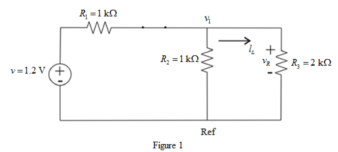
Refer to the redrawn Figure 1.
The given circuit inductor is connected for 6 years prior to being flipped open at
Apply KCL at node 1.
Here,
Substitute
Rearrange the above equation for
The voltage across
Substitute
Conclusion:
Thus, at
(b)
Find the value of
(b)
Answer to Problem 28E
At
Explanation of Solution
Calculation:
The redrawn circuit diagram is given in Figure 2.
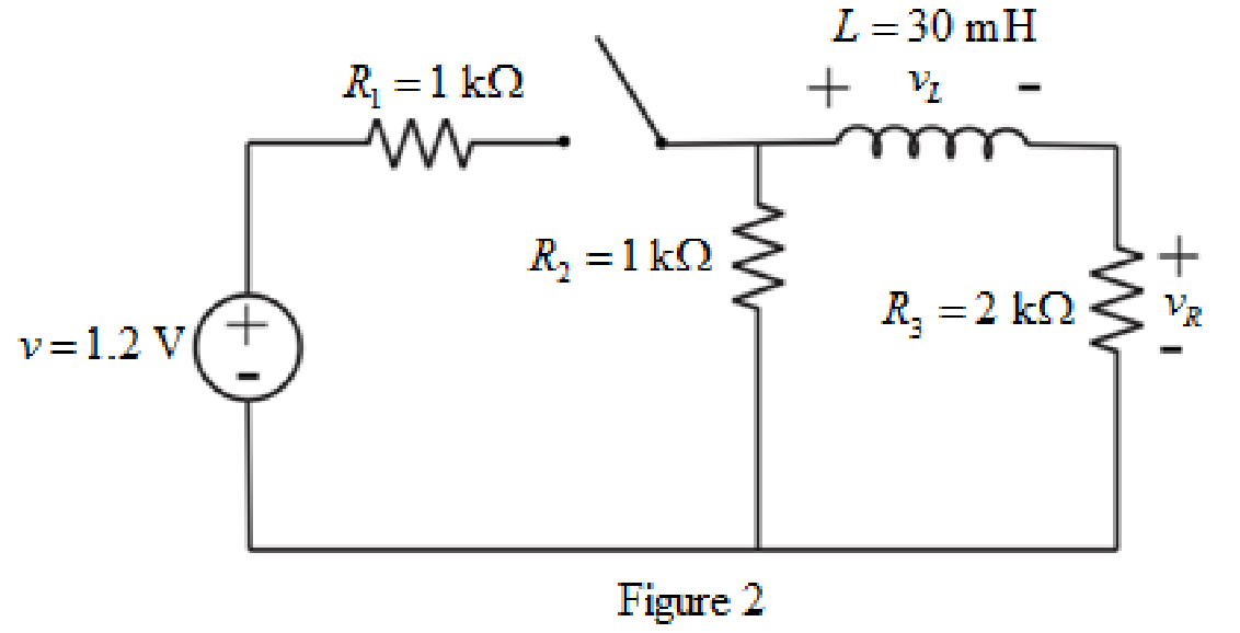
Refer to the redrawn Figure 2.
The expression for the voltage across the
Here,
Refer to the redrawn Figure 2.
The inductor does not allow sudden change in the current.
So, the current through inductor at
Apply KVL in the right side mesh.
Here,
Substitute
Rearrange for
Substitute
Conclusion:
Thus, at
(c)
Find the value of
(c)
Answer to Problem 28E
At
Explanation of Solution
Given data:
The time is
Formula used:
The expression for the equivalent resistor connected in series is as follows.
Here,
The expression for the time constant for
Here,
The expression for the current for
Here,
Calculation:
The redrawn circuit diagram is given in Figure 3.
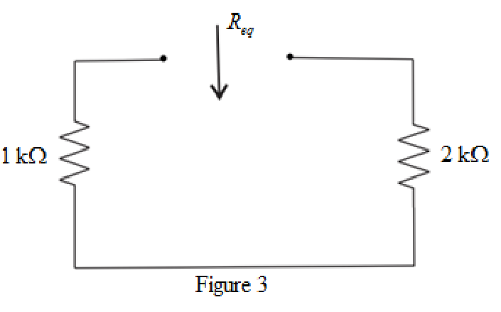
Refer to the redrawn Figure 3.
The simplified diagram is shown in Figure 4.
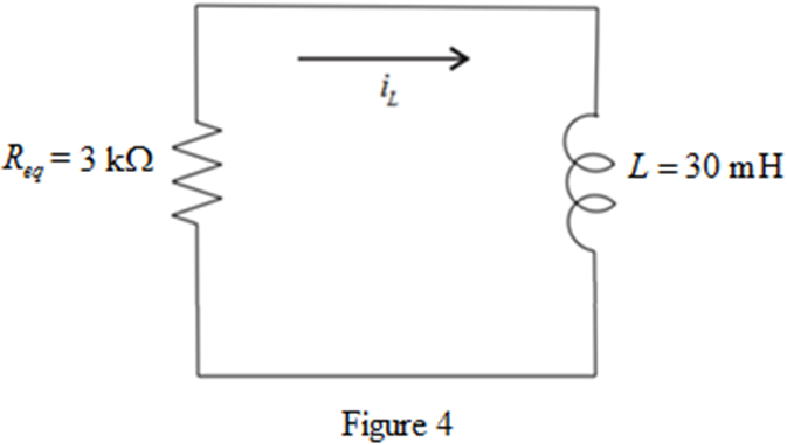
Refer to the redrawn Figure 4.
Substitute
Substitute
Substitute
Rearrange the above equation for
Substitute
Conclusion:
Thus, at
(d)
Find the value of
(d)
Answer to Problem 28E
At
Explanation of Solution
Given Data:
The time is
Calculation:
Substitute
Substitute
Rearrange the above equation for
Substitute
Conclusion:
Thus, at
Want to see more full solutions like this?
Chapter 8 Solutions
Loose Leaf for Engineering Circuit Analysis Format: Loose-leaf


- 8.23 At t=0 s, a 100-V source is switched in series with a 1-k resistor and an uncharged 2-µF capacitor. What are (a) the initial capacitor voltage, (b) the initial current, (c) the initial rate of capacitor voltage increase, and (d) the time required for the capacitor voltage to reach its maximum value?arrow_forwarda. Determine time constant(t). b. Write the mathematical expression for the current iL after the switch is closed at t = 0 s. c. Write the mathematical expression for VL and VR after the switch is closed at t = 0 s. d. Determine iL and VL at t = 1t, 3t, and 5t e. Sketch the waveforms of iL, VL, and VR for the. storage phase. Please answer all subpart in typing format please Not only three subpart I will dislike Pleasearrow_forward8. 7.8 In the circuit the voltage and current expressions are v=400e−5tV, t≥0+;i=10e−5tA, t≥0. 5. e) the time (in milliseconds) it takes to dissipate 80% of the initialstored energy.arrow_forward
- Problem 2 (Exercise 2.8.8) A single-loop LC circuit (where R = 0) has L = 4 H and C = 0.25 F. The voltage source is a 2-V battery that is shorted out (e = 0) after 4л seconds. The initial charge is zero and the initial current is 1 A. Find the charge on the capacitor and current in the inductor for 0 ≤ t ≤ 8ë. (Assume that the charge and current are continuous at t 4л.) =arrow_forward4. A series RL circuit has a square wave Vs as input: (a) Draw the graph of voltage VL. Note: the inductor is fully discharged at t=0. (b) Draw the graph of voltage VR. (c) Draw the graph of current I through the resistor R. NOTE :Make sure to show all values on your waveforms. ( Vp-p.A,B,T,T/2, the time constant, ect)arrow_forward8. A 62.5-µf capacitor is connected in series with a 200,000-ohm resistor and to a 250-volt d-c source. (a) Write the expression for the charging current following the closing of the switch. (b) What is the initial charging current? (c) Calculate the time constant and the charging current at t = t. (d) What will be the initial rate of current change?arrow_forward
- If in a circuit, E=9v and the current I reaches half its maximum value of 2A at t=0.1s after the switch is closed. What is the time constant of the circuit? What is the emf across the inductor at t=0.1s?arrow_forwardConsider a series RC circuit as in the figure below for which R = 3.00 MN, C = 4.00 PF, and E = 29.0 v. S R (a) Find the time constant of the circuit. (b) What is the maximum charge on the capacitor after the switch is thrown closed? (c) Find the current in the resistor 10.0 s after the switch is closed. HAarrow_forwardIn the circuit, V is a 3.4 V battery, C is a 71.3 µC capacitor, L is a 29.6 mH coil (with no resistance), R1 = R3 = R4 = 3.99 N, R2 = 6.78 N and S is a switch, initially open. At t = 0 the switch is closed. At that instant: find dljdt, the rate at which the current is changing in the coil, in A/s. The sign of the answer will indicate if / is increasing or decreasing. %3D Diagram 3 V R4 R2 R3 R1 GOD000-arrow_forward
- 8.3.1 For the RLC circuit shown in the image below, if R1 = 3 2 and R2 = 7 2, C = 0.44 F, and the power source Vs = 7 V, determine the initial value iL (0* ). Please pay attention: the numbers may change since they are randomized. Your answer must include 2 places after the decimal point, and proper SI unit. R2 + 2u(t) A R Vs Your Answer: Answer units 118 llarrow_forwardAn RLC circuit is composed of a 30,a 500 mH Induc tor, ond a 200 MF copacitor. If the capactar is initially charged with a 90 V volt source while the switch is Open, what will be the currént in the circuit 0.04 seconds after the switch is closed (removing the volt source from the Circuit)?arrow_forwardThe RC circuit shown on the right consists of a 1 µF capacitance, with an initial stored energy of 450 µµJ and a lkN resistance. If the circuit is subjected to a dc forcing voltage Vs, and if it is found that v(2 ms) = 0 a) Find Vs b) How much voltage changes v(t = 0.1ms) to v(t=lms)arrow_forward
 Introductory Circuit Analysis (13th Edition)Electrical EngineeringISBN:9780133923605Author:Robert L. BoylestadPublisher:PEARSON
 Delmar's Standard Textbook Of ElectricityElectrical EngineeringISBN:9781337900348Author:Stephen L. HermanPublisher:Cengage Learning
 Programmable Logic ControllersElectrical EngineeringISBN:9780073373843Author:Frank D. PetruzellaPublisher:McGraw-Hill Education
 Fundamentals of Electric CircuitsElectrical EngineeringISBN:9780078028229Author:Charles K Alexander, Matthew SadikuPublisher:McGraw-Hill Education
 Electric Circuits. (11th Edition)Electrical EngineeringISBN:9780134746968Author:James W. Nilsson, Susan RiedelPublisher:PEARSON
 Engineering ElectromagneticsElectrical EngineeringISBN:9780078028151Author:Hayt, William H. (william Hart), Jr, BUCK, John A.Publisher:Mcgraw-hill Education,