
Loose Leaf for Engineering Circuit Analysis Format: Loose-leaf
9th Edition
ISBN: 9781259989452
Author: Hayt
Publisher: Mcgraw Hill Publishers
expand_more
expand_more
format_list_bulleted
Concept explainers
Videos
Textbook Question
Chapter 8, Problem 60E
For the circuit given in Fig. 8.85, (a) determine vL(0−), vL(0+), iL(0−), and iL(0+); (b) calculate iL(150 ns). (c) Verify your answer to part (b) with an appropriate SPICE simulation.
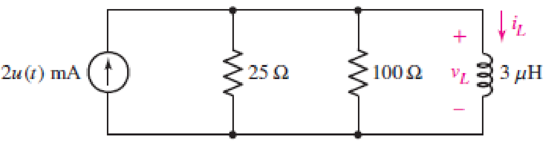
■ FIGURE 8.85
Expert Solution & Answer
Want to see the full answer?
Check out a sample textbook solution
Students have asked these similar questions
8.1 For the network below determine a) I, and I,; b) V,
2Ω ν.
6 A R
{ 80
Explain with the aid of illustrations the relationships of voltage and current in the following AC circuits: (a) purely resistive circuit; (b) purely inductive circuit; (c) purely capacitive circuit; (d) series RLC circuit.
R₁
w
£₁10 V R₂10
R₁
ww
40
HI
R. SA
FIG. 8.121
Rs
www
30
E₂2=6V
Chapter 8 Solutions
Loose Leaf for Engineering Circuit Analysis Format: Loose-leaf
Ch. 8.1 - For the circuit in Fig. 8.2, what value of...Ch. 8.1 - Noting carefully how the circuit changes once the...Ch. 8.2 - In a source-free series RC circuit, find the...Ch. 8.3 - Prob. 4PCh. 8.3 - Prob. 5PCh. 8.4 - Prob. 6PCh. 8.4 - Prob. 7PCh. 8.4 - Prob. 8PCh. 8.5 - Evaluate each of the following at t = 0.8: (a)...Ch. 8.6 - For the circuit of Fig. 8.37, find vc(t) at t...
Ch. 8.7 - Prob. 11PCh. 8.7 - The voltage source 60 40u(t) V is in series with...Ch. 8.7 - Prob. 13PCh. 8.8 - Prob. 14PCh. 8.8 - Prob. 15PCh. 8 - A source-free RC circuit has R = 4 k and C = 22 F,...Ch. 8 - A source-free RC circuit has v(0) = 12 V and R =...Ch. 8 - The resistor in the circuit of Fig. 8.51 has been...Ch. 8 - Prob. 4ECh. 8 - Prob. 5ECh. 8 - Prob. 6ECh. 8 - Prob. 7ECh. 8 - Prob. 8ECh. 8 - Prob. 9ECh. 8 - The switch in Fig. 8.56 has been closed for a long...Ch. 8 - For the circuit in Fig. 8.56, find (a) the total...Ch. 8 - Design a capacitor-based circuit that can achieve...Ch. 8 - (a) Graph the function f (t) = 10e2t over the...Ch. 8 - The current i(t) flowing through a 1 k resistor is...Ch. 8 - Radiocarbon dating has a similar exponential time...Ch. 8 - For the circuit of Fig. 8.4, compute the time...Ch. 8 - Design a circuit which will produce a current of 1...Ch. 8 - Prob. 18ECh. 8 - Prob. 19ECh. 8 - Referring to the circuit shown in Fig. 8.11,...Ch. 8 - Prob. 21ECh. 8 - With the assumption that the switch in the circuit...Ch. 8 - The switch in Fig. 8.57 has been closed since...Ch. 8 - The switch in the circuit of Fig. 8.58 has been...Ch. 8 - Assuming the switch initially has been open for a...Ch. 8 - (a) Obtain an expression for v(t), the voltage...Ch. 8 - For the circuit of Fig. 8.61, determine ix, iL,...Ch. 8 - Prob. 28ECh. 8 - Prob. 29ECh. 8 - Prob. 30ECh. 8 - Prob. 31ECh. 8 - (a) Obtain an expression for vx as labeled in the...Ch. 8 - Prob. 33ECh. 8 - Prob. 34ECh. 8 - Prob. 35ECh. 8 - Prob. 36ECh. 8 - Prob. 37ECh. 8 - The switch in Fig. 8.70 is moved from A to B at t...Ch. 8 - Prob. 39ECh. 8 - Prob. 40ECh. 8 - Evaluate the following functions at t = 1, 0, and...Ch. 8 - Prob. 42ECh. 8 - Prob. 43ECh. 8 - Prob. 44ECh. 8 - You can use MATLAB to represent the unit-step...Ch. 8 - With reference to the circuit depicted in Fig....Ch. 8 - For the circuit given in Fig. 8.75, (a) determine...Ch. 8 - Prob. 48ECh. 8 - Prob. 49ECh. 8 - You build a portable solar charging circuit...Ch. 8 - The switch in the circuit of Fig. 8.78 has been...Ch. 8 - The switch in the circuit of Fig. 8.78 has been...Ch. 8 - Prob. 53ECh. 8 - Prob. 54ECh. 8 - Prob. 55ECh. 8 - For the circuit represented in Fig. 8.82, (a)...Ch. 8 - Prob. 58ECh. 8 - Prob. 59ECh. 8 - For the circuit given in Fig. 8.85, (a) determine...Ch. 8 - The circuit depicted in Fig. 8.86 contains two...Ch. 8 - Prob. 62ECh. 8 - Prob. 63ECh. 8 - A series RL circuit has a voltage that steps from...Ch. 8 - For the two-source circuit of Fig. 8.89, note that...Ch. 8 - (a) Obtain an expression for iL as labeled in Fig....Ch. 8 - Obtain an expression for i(t) as labeled in the...Ch. 8 - Obtain an expression for i1 as indicated in Fig....Ch. 8 - Plot the current i(t) in Fig. 8.93 if (a) R = 10 ;...Ch. 8 - A dc motor can be modeled as a series RL circuit...Ch. 8 - Prob. 71ECh. 8 - Prob. 72ECh. 8 - A series RC sequentially switched circuit has R =...Ch. 8 - Refer to the circuit of Fig. 8.95, which contains...Ch. 8 - In the circuit of Fig. 8.95, a 3 mF capacitor is...Ch. 8 - Prob. 78E
Knowledge Booster


Learn more about
Need a deep-dive on the concept behind this application? Look no further. Learn more about this topic, electrical-engineering and related others by exploring similar questions and additional content below.Similar questions
- For the circuit drawn in Figure 8, where V,(t) = 400 cos(400t + 16.26°) V and I,(t) = 4/2 cos(500t – 135°) A, find the voltage v-(t). 2002 20µF vz(t) 800mH V,(t) (2)*I 400m H Figure 8:arrow_forward8. The PMOS in the image below, is specified to have Vth = -1V and kp = 0.4/V 2. The ideal current source has 1 = 0.2mA. Find the voltage Vx. 10V 5ΚΩ ↓arrow_forwardQ.2 Write TRUE or FALSE then correct the false ones for the following 1. Photoresistor is a solid-state device which converts incident light into an electric current. It is made of Silicon and consisted of a shallow diffused p-n junction. 2. Thermocouple is made of two wires which are composed of dissimilar metals are joined at both ends and one of the ends is heated. 3. Tactile sensors have two PVDF layers separated by a soft film which transmits the motion. 4. Diaphragms, capsules, and bellows are used to monitor the vacuum pressure. 5. Photo emitting devices are used as proximity switches. When a magnet attached to an object brought close to the switch, the magnetic reeds attract to each other and close the switch contacts. 6. LVDT has three coils symmetrically spaced along an insulated tube. The central coil is primary coil and the other two are secondary coils.arrow_forward
- 8.3 For a Si solar cell, the dark saturation current is 2 μA and the short circuit cur- rent is 150 mA. When it is optically illuminated, the optically generated current is 0.1 mA. Find the corresponding voltage at current of 100 mA. please tell me his problem in detailarrow_forwardThis circuit is used to measure the speed of a bullet with elements of the following values: Vo = 100 V, R = 25 N, C = 100 µF, d = 10 cm. R A B R C I Initially, the capacitor is charged, then the bullet cuts wire A disconnecting the battery, and later cuts wire B, leaving the capacitor isolated, whose potential difference, once both wires have been cut, is Vo / 4 a) Calculate the potential difference across the capacitor before the bullet cuts the wires, assuming the battery has been connected for a long time (show all steps). b) Determine the speed of the bullet (show all steps). c) Plot the current through the capacitor as a function of time (show all steps).arrow_forwardExample A series AC circuit is shown in Fig. 8. Calculate the source current, apparent, real and reactive powers. The expression of the alternating voltage source is v(t) = 16 sin(10t+25°) V. %3D i(1) 42 (1)A 0.9H Figure 8.arrow_forward
- A circuit element has the following voltage across it and current running through it.?(?) = 3 cos(100? + 30°) V,?(?) = 50sin(100? + 30°) mA.Assume polarities are chosen so that the current is flowing into the positive voltage terminal.(a) Determine if this circuit element is a resistor, capacitor, or inductor.(b) Find the impedance of this circuit element.(c) Find the component value of the circuit element. ie. if it is an resistor find R, if it is a capacitor, find C, if it is an inductor, find L.arrow_forwardAn electric circuit contains an 8 ohm resistor in series with an inductor of 0.50 henries and a battery of E volts. At t=0 the current is zero. Find the current at any time t > 0 and the maximum current if (a) E=64, (b) E=8te-16t, (c) E=32e-8t, (d) E = 64sin8tarrow_forwarda series rlc circuit having values of pure resistance r=40 ohms and pure inductance l = 50.07 mh. the circuit draws 10 A of current when it is connected across a 400 v , 50hz ,ac supply. calculate the (1) capacitor value and (2) power factor of circuit.arrow_forward
- .ull ZAIN IQ 8:42 PM 1 45% A docs.google.com 4-For the circuit shown in Figure, Using nodal analysis, to determine the current in (30) ? * SA 16 V 6V SA O (I= 8 A ) & ( R=2 0) (1= - 8 A) & ( R=40) O (1= 6 A ) & ( R=4 Q) Page 2 of 2 Вack Submit Never submit passwords through Google Forms. This form was created inside of University of Kerbala. Report Abuse Google Formsarrow_forwardPlot the input and output graphs, label them completely. (IGT=0.8ma; VGT=0.6V). Compute the firing angle for the following settings. a. RG is @10% setting b. Rg is @ 30% setting c. RG is @ 50% settingarrow_forwardShown below is a typical setup for a solar battery system. Sun’s energy is converted to electricity using solar PV modules. To match the output voltage of the PV module to the battery's, a charge controller is used which is a DC-DC converter. The sun’s output power is given as 1000 W/m2. The solar module has a surface area of 1 m^2 with a conversion efficiency of 10%. A charge controller converts the 20V module voltage to 12V battery voltage, with an efficiency of 84% The battery is 12V with a capacity of 10Ah. Assuming the battery is half empty (or half full, depending on your personality) and the bulb is powered on, how long will it take for the battery to be fully charged? How long can the bulb be powered at night, assuming full battery when the sun goes down and that you can fully drain the battery? (answer in hours)arrow_forward
arrow_back_ios
SEE MORE QUESTIONS
arrow_forward_ios
Recommended textbooks for you
 Introductory Circuit Analysis (13th Edition)Electrical EngineeringISBN:9780133923605Author:Robert L. BoylestadPublisher:PEARSON
 Delmar's Standard Textbook Of ElectricityElectrical EngineeringISBN:9781337900348Author:Stephen L. HermanPublisher:Cengage Learning
 Programmable Logic ControllersElectrical EngineeringISBN:9780073373843Author:Frank D. PetruzellaPublisher:McGraw-Hill Education
 Fundamentals of Electric CircuitsElectrical EngineeringISBN:9780078028229Author:Charles K Alexander, Matthew SadikuPublisher:McGraw-Hill Education
 Electric Circuits. (11th Edition)Electrical EngineeringISBN:9780134746968Author:James W. Nilsson, Susan RiedelPublisher:PEARSON
 Engineering ElectromagneticsElectrical EngineeringISBN:9780078028151Author:Hayt, William H. (william Hart), Jr, BUCK, John A.Publisher:Mcgraw-hill Education,
Introductory Circuit Analysis (13th Edition)
Electrical Engineering
ISBN:9780133923605
Author:Robert L. Boylestad
Publisher:PEARSON
Delmar's Standard Textbook Of Electricity
Electrical Engineering
ISBN:9781337900348
Author:Stephen L. Herman
Publisher:Cengage Learning
Programmable Logic Controllers
Electrical Engineering
ISBN:9780073373843
Author:Frank D. Petruzella
Publisher:McGraw-Hill Education
Fundamentals of Electric Circuits
Electrical Engineering
ISBN:9780078028229
Author:Charles K Alexander, Matthew Sadiku
Publisher:McGraw-Hill Education
Electric Circuits. (11th Edition)
Electrical Engineering
ISBN:9780134746968
Author:James W. Nilsson, Susan Riedel
Publisher:PEARSON
Engineering Electromagnetics
Electrical Engineering
ISBN:9780078028151
Author:Hayt, William H. (william Hart), Jr, BUCK, John A.
Publisher:Mcgraw-hill Education,
ENA 9.2(1)(En)(Alex) Sinusoids & Phasors - Explanation with Example 9.1 ,9.2 & PP 9.2; Author: Electrical Engineering Academy;https://www.youtube.com/watch?v=vX_LLNl-ZpU;License: Standard YouTube License, CC-BY
Electrical Engineering: Ch 10 Alternating Voltages & Phasors (8 of 82) What is a Phasor?; Author: Michel van Biezen;https://www.youtube.com/watch?v=2I1tF3ixNg0;License: Standard Youtube License