
Loose Leaf for Engineering Circuit Analysis Format: Loose-leaf
9th Edition
ISBN: 9781259989452
Author: Hayt
Publisher: Mcgraw Hill Publishers
expand_more
expand_more
format_list_bulleted
Concept explainers
Videos
Textbook Question
Chapter 8, Problem 25E
Assuming the switch initially has been open for a really, really long time, (a) obtain an expression for iW in the circuit of Fig. 8.59, which is valid for all t ≥ 0; (b) calculate iW at t = 0 and t = 1.3 ns.
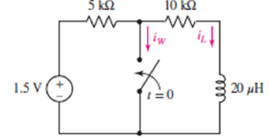
Figure 8.59
Expert Solution & Answer
Want to see the full answer?
Check out a sample textbook solution
Students have asked these similar questions
With any computational method that graphs transients, plot a graph of current "i" for 0<t<1 seconds, if v(0)=6v and i(0)=2A. No calculation is needed, just the current graph.
2.
Consider the following electrical system:
R
L
C= Uc
The equations describing the system dynamics are the following:
di(t)
u(t) = Lº
+(R, +R, )i(t)+u̟(t)
dt
c du (t)
= i(t)
dt
Choose as state variables: x, (t) = u.(t) and x, (t) = i(t).
Obtain the following state space model
1
-
C
+ 1 u
R, + R, |X2
L
1
L
y =[1 0]
+ Ou
and calculate the system matrices for L = 0.5, R1 = 1, R2 = 1and C = 1.
From the state space model obtain the transfer function of the system.
By using controllability gramian, check if the system representation R(A,B,C) is
controllable.
Design a state feedback u(t) = -Kx(t), which will place the closed-loop poles on
desired locations: 14 = -1 and 14 = -2.
By using observability matrix, check if the system representation R(A, B,C) is
observable.
Design a reduced-order state observer with desired poles 2d = -2.
If the switch in the figure was closed for a long time and opens at t = 0, find:a) v(0), wc(0)b) Constant of time t
c) v(t), ic(t)
Chapter 8 Solutions
Loose Leaf for Engineering Circuit Analysis Format: Loose-leaf
Ch. 8.1 - For the circuit in Fig. 8.2, what value of...Ch. 8.1 - Noting carefully how the circuit changes once the...Ch. 8.2 - In a source-free series RC circuit, find the...Ch. 8.3 - Prob. 4PCh. 8.3 - Prob. 5PCh. 8.4 - Prob. 6PCh. 8.4 - Prob. 7PCh. 8.4 - Prob. 8PCh. 8.5 - Evaluate each of the following at t = 0.8: (a)...Ch. 8.6 - For the circuit of Fig. 8.37, find vc(t) at t...
Ch. 8.7 - Prob. 11PCh. 8.7 - The voltage source 60 40u(t) V is in series with...Ch. 8.7 - Prob. 13PCh. 8.8 - Prob. 14PCh. 8.8 - Prob. 15PCh. 8 - A source-free RC circuit has R = 4 k and C = 22 F,...Ch. 8 - A source-free RC circuit has v(0) = 12 V and R =...Ch. 8 - The resistor in the circuit of Fig. 8.51 has been...Ch. 8 - Prob. 4ECh. 8 - Prob. 5ECh. 8 - Prob. 6ECh. 8 - Prob. 7ECh. 8 - Prob. 8ECh. 8 - Prob. 9ECh. 8 - The switch in Fig. 8.56 has been closed for a long...Ch. 8 - For the circuit in Fig. 8.56, find (a) the total...Ch. 8 - Design a capacitor-based circuit that can achieve...Ch. 8 - (a) Graph the function f (t) = 10e2t over the...Ch. 8 - The current i(t) flowing through a 1 k resistor is...Ch. 8 - Radiocarbon dating has a similar exponential time...Ch. 8 - For the circuit of Fig. 8.4, compute the time...Ch. 8 - Design a circuit which will produce a current of 1...Ch. 8 - Prob. 18ECh. 8 - Prob. 19ECh. 8 - Referring to the circuit shown in Fig. 8.11,...Ch. 8 - Prob. 21ECh. 8 - With the assumption that the switch in the circuit...Ch. 8 - The switch in Fig. 8.57 has been closed since...Ch. 8 - The switch in the circuit of Fig. 8.58 has been...Ch. 8 - Assuming the switch initially has been open for a...Ch. 8 - (a) Obtain an expression for v(t), the voltage...Ch. 8 - For the circuit of Fig. 8.61, determine ix, iL,...Ch. 8 - Prob. 28ECh. 8 - Prob. 29ECh. 8 - Prob. 30ECh. 8 - Prob. 31ECh. 8 - (a) Obtain an expression for vx as labeled in the...Ch. 8 - Prob. 33ECh. 8 - Prob. 34ECh. 8 - Prob. 35ECh. 8 - Prob. 36ECh. 8 - Prob. 37ECh. 8 - The switch in Fig. 8.70 is moved from A to B at t...Ch. 8 - Prob. 39ECh. 8 - Prob. 40ECh. 8 - Evaluate the following functions at t = 1, 0, and...Ch. 8 - Prob. 42ECh. 8 - Prob. 43ECh. 8 - Prob. 44ECh. 8 - You can use MATLAB to represent the unit-step...Ch. 8 - With reference to the circuit depicted in Fig....Ch. 8 - For the circuit given in Fig. 8.75, (a) determine...Ch. 8 - Prob. 48ECh. 8 - Prob. 49ECh. 8 - You build a portable solar charging circuit...Ch. 8 - The switch in the circuit of Fig. 8.78 has been...Ch. 8 - The switch in the circuit of Fig. 8.78 has been...Ch. 8 - Prob. 53ECh. 8 - Prob. 54ECh. 8 - Prob. 55ECh. 8 - For the circuit represented in Fig. 8.82, (a)...Ch. 8 - Prob. 58ECh. 8 - Prob. 59ECh. 8 - For the circuit given in Fig. 8.85, (a) determine...Ch. 8 - The circuit depicted in Fig. 8.86 contains two...Ch. 8 - Prob. 62ECh. 8 - Prob. 63ECh. 8 - A series RL circuit has a voltage that steps from...Ch. 8 - For the two-source circuit of Fig. 8.89, note that...Ch. 8 - (a) Obtain an expression for iL as labeled in Fig....Ch. 8 - Obtain an expression for i(t) as labeled in the...Ch. 8 - Obtain an expression for i1 as indicated in Fig....Ch. 8 - Plot the current i(t) in Fig. 8.93 if (a) R = 10 ;...Ch. 8 - A dc motor can be modeled as a series RL circuit...Ch. 8 - Prob. 71ECh. 8 - Prob. 72ECh. 8 - A series RC sequentially switched circuit has R =...Ch. 8 - Refer to the circuit of Fig. 8.95, which contains...Ch. 8 - In the circuit of Fig. 8.95, a 3 mF capacitor is...Ch. 8 - Prob. 78E
Knowledge Booster


Learn more about
Need a deep-dive on the concept behind this application? Look no further. Learn more about this topic, electrical-engineering and related others by exploring similar questions and additional content below.Similar questions
- For the circuit in Figure 3 the switch is in the left position for several minutes: (a) Find the Initlal voltage, o on the capacitor just before the switch is flipped (b) Find an expression v(t) that describes the voltage across the 20 N resistor after the switch has been Figure 3 1Ω 60 N flipped to the right NOTE: Remember what we said in class: use a Circuit-Specific Equation to get a value you know. Then solve for whatever else the problem asks for O 12 V 5 2 -50 μF 80 Ω 20Ωarrow_forward8002 80V t=0 3F 0.5i(t) 30Ω www 5002 vi(t) The switch in the circuit has been closed for a long time. At t=0 the switch opens. a) Determine the voltage across the capacitor at t-0 b) For t>0, determine the resistance seen at the terminals of the capacitor and the time constant of the circuit. c) Determine i(t) for t>0.arrow_forward2. Consider the following electrical system: R Uc C = i The equations describing the system dynamics are the following: di(t) +(R, + R, )i(t)+u (t) dt u(t) = L- c du (t) C- = i(t) dt Choose as state variables: x, (t) =u¸(t) and x, (t) = i(t). %D Obtain the following state space model 1 + 1 u 1 R + R, Lx2 L y = [1 0] + Ou X2 and calculate the system matrices for L = 1, R1 = 1, R2 = 1and C = 0.5. From the state space model obtain the transfer function of the system. By using controllability gramian, check if the system representation R(A,B,C) is controllable. ||arrow_forward
- For the circuit in Figure 3 the switch is in the left position for several minutes: (a) Find the Initlal voltage, V, on the capacitor just before the switch is flipped (b) Find an expression v(t) that describes the voltage across the 20 N resistor after the switch has been Figure 3 U 09 flipped to the right NOTE: Remember what we said in class: use a Circuit-Specific Equation to get a value you know. Then solve for whatever else the problem asks for +50 µF 380 0 20 2arrow_forward3. The switch in the following circuit has been in position a for a long time and instantaneously moves to position b at t = 0. a. Determine the current, i (t), with the switch in position a (i.e. for t = 0-). b. Determine i (t) just after the switch moves to b and after a long time (i.e. t= 0* and t = ). c. Determine the time constant, t, for the switch in position b. d. Write out the equation for the i (t), for t> 0. e. Plot the current i (t) for t> 0. a 4kQ 2500 5kn t = 0 12V 15ka 20V | 340mHarrow_forward9. 7.3.13 Find vc(t) for t> 0 in the given circuit if vc(0) = 0. 12 V ·0 1k0 100 mH mm 1 μF (1)arrow_forward
- The following circuit is used by a biology student to study "frog kick." She noticed that the frog kicked a little when the switch was closed but kicked violently when the switch was opened. Model the frog as a resistor (Rfrog = 1000N). Assume that switch has been closed for a long time. a) Compute the initial inductor current under DC conditions. b) At t = Os the switch is opened. Compute inductor current for t > 0. c) What is voltage applied to frog for t > 0? What could be a possible reason for the frog's violent kick? Switch 50 2 Frog 12 V 2 H |arrow_forwardL= 270 mHC= 860 uF For circuit; a) Find the time constant for t> 0. b) Find the equation for İ0 (t) for time t> 0. c) Find the equation V0(t) for time t> 0.arrow_forwardThank youarrow_forward
- Figure 8 showsa resistor inductor capacitor (RLC) circuit. The input to the system is the voltage v(t) and the output of the circuit is the current iz (t). 8 R, i(t) iz(t) v(t) Ve(t) R2 Figure 8 a) Determine differential equations containing i, (t), iz (t) and v. (t) for the appropriate meshes and nodes. b) Assuming zero initial conditions i) derive Laplace transformations of the differential equations found in a) ii) determine the transfer function G(s) = I2(s) VIs where l2(s) = L{i2 (t}} and V(s) = L{v(t}.arrow_forwarda). Find V(t) in the circuit for all time t> 0 and t < 0. Assume that the switch has been open for a long time and is closed at t = 0. 1=0 ww 10 V 40= 0.5 F 3 20arrow_forward3) Consider the circuit below. Assume the switch has been in its initial position for a long time, and it switches position as indicated at t = 0. a. Find v(t) for all t > 0. b. Sketch v(t) as voltage vs. time; annotate critical values on your sketch (see video lectures for example). C. How much energy is stored in the capacitor at t = 0? + ww 50 ΚΩ 12 V t = 0 100 ΚΩ M 100 μF + v(t)arrow_forward
arrow_back_ios
SEE MORE QUESTIONS
arrow_forward_ios
Recommended textbooks for you
 Introductory Circuit Analysis (13th Edition)Electrical EngineeringISBN:9780133923605Author:Robert L. BoylestadPublisher:PEARSON
 Delmar's Standard Textbook Of ElectricityElectrical EngineeringISBN:9781337900348Author:Stephen L. HermanPublisher:Cengage Learning
 Programmable Logic ControllersElectrical EngineeringISBN:9780073373843Author:Frank D. PetruzellaPublisher:McGraw-Hill Education
 Fundamentals of Electric CircuitsElectrical EngineeringISBN:9780078028229Author:Charles K Alexander, Matthew SadikuPublisher:McGraw-Hill Education
 Electric Circuits. (11th Edition)Electrical EngineeringISBN:9780134746968Author:James W. Nilsson, Susan RiedelPublisher:PEARSON
 Engineering ElectromagneticsElectrical EngineeringISBN:9780078028151Author:Hayt, William H. (william Hart), Jr, BUCK, John A.Publisher:Mcgraw-hill Education,
Introductory Circuit Analysis (13th Edition)
Electrical Engineering
ISBN:9780133923605
Author:Robert L. Boylestad
Publisher:PEARSON
Delmar's Standard Textbook Of Electricity
Electrical Engineering
ISBN:9781337900348
Author:Stephen L. Herman
Publisher:Cengage Learning
Programmable Logic Controllers
Electrical Engineering
ISBN:9780073373843
Author:Frank D. Petruzella
Publisher:McGraw-Hill Education
Fundamentals of Electric Circuits
Electrical Engineering
ISBN:9780078028229
Author:Charles K Alexander, Matthew Sadiku
Publisher:McGraw-Hill Education
Electric Circuits. (11th Edition)
Electrical Engineering
ISBN:9780134746968
Author:James W. Nilsson, Susan Riedel
Publisher:PEARSON
Engineering Electromagnetics
Electrical Engineering
ISBN:9780078028151
Author:Hayt, William H. (william Hart), Jr, BUCK, John A.
Publisher:Mcgraw-hill Education,
ENA 9.2(1)(En)(Alex) Sinusoids & Phasors - Explanation with Example 9.1 ,9.2 & PP 9.2; Author: Electrical Engineering Academy;https://www.youtube.com/watch?v=vX_LLNl-ZpU;License: Standard YouTube License, CC-BY
Electrical Engineering: Ch 10 Alternating Voltages & Phasors (8 of 82) What is a Phasor?; Author: Michel van Biezen;https://www.youtube.com/watch?v=2I1tF3ixNg0;License: Standard Youtube License