
Loose Leaf for Engineering Circuit Analysis Format: Loose-leaf
9th Edition
ISBN: 9781259989452
Author: Hayt
Publisher: Mcgraw Hill Publishers
expand_more
expand_more
format_list_bulleted
Concept explainers
Videos
Textbook Question
Chapter 8, Problem 46E
With reference to the circuit depicted in Fig. 8.74, compute v(t) for (a) t = 0−; (b) t = 0+; (c) t = 2 ms; (d) t = 5 ms.
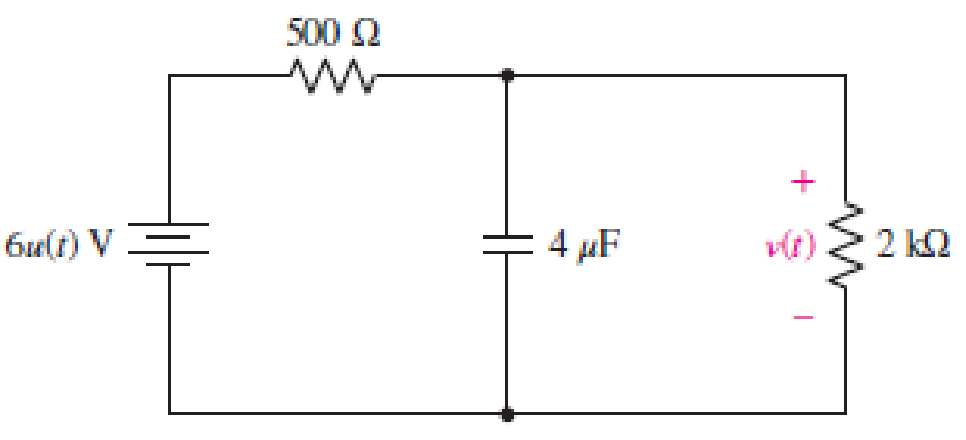
FIGURE 8.74
Expert Solution & Answer
Want to see the full answer?
Check out a sample textbook solution
Students have asked these similar questions
8.4 Step-Response Series
RLC Circuits (3)
Example 4
Having been in position for a long time, the
switch in the circuit below is moved to position b
at t = 0. Find v(t) and vR(t) for t > 0.
2.5 H
10Ω
a
ww-
12 V
22
10 V
• Please refer to lecture or textbook for more detail elaboration.
Answer: v(t) = {10 + [(-2cos3.464t – 1.1547sin3.464t)e-2t]} V
VR(t)= [2.31sin3.464t]e-2t V
15
-19
ww
The switch in Fig. 8.73 is moved from A to B at t = 0 after being at A for along time. This places the two capacitors in series, thus allowing equal andopposite dc voltages to be trapped on the capacitors. (a) Determine v1(0−),v2(0−), and vR(0−). (b) Find v1(0+), v2(0+), and vR(0+). (c) Determine thetime constant of vR(t). (d) Find vR(t), t > 0. (e) Find i(t). ( f ) Find v1(t) andv2(t) from i(t) and the initial values. (g) Show that the stored energy at t = ∞plus the total energy dissipated in the 20 k-resistor is equal to the energystored in the capacitors at t = 0.
Figure 8 showsa resistor inductor capacitor (RLC) circuit. The input to the system is
the voltage v(t) and the output of the circuit is the current iz (t).
8
R,
i(t)
iz(t)
v(t)
Ve(t)
R2
Figure 8
a)
Determine differential equations containing i, (t), iz (t) and v. (t) for the
appropriate meshes and nodes.
b) Assuming zero initial conditions
i)
derive Laplace transformations of the differential equations found in a)
ii)
determine the transfer function G(s) =
I2(s)
VIs where l2(s) = L{i2 (t}}
and V(s) = L{v(t}.
Chapter 8 Solutions
Loose Leaf for Engineering Circuit Analysis Format: Loose-leaf
Ch. 8.1 - For the circuit in Fig. 8.2, what value of...Ch. 8.1 - Noting carefully how the circuit changes once the...Ch. 8.2 - In a source-free series RC circuit, find the...Ch. 8.3 - Prob. 4PCh. 8.3 - Prob. 5PCh. 8.4 - Prob. 6PCh. 8.4 - Prob. 7PCh. 8.4 - Prob. 8PCh. 8.5 - Evaluate each of the following at t = 0.8: (a)...Ch. 8.6 - For the circuit of Fig. 8.37, find vc(t) at t...
Ch. 8.7 - Prob. 11PCh. 8.7 - The voltage source 60 40u(t) V is in series with...Ch. 8.7 - Prob. 13PCh. 8.8 - Prob. 14PCh. 8.8 - Prob. 15PCh. 8 - A source-free RC circuit has R = 4 k and C = 22 F,...Ch. 8 - A source-free RC circuit has v(0) = 12 V and R =...Ch. 8 - The resistor in the circuit of Fig. 8.51 has been...Ch. 8 - Prob. 4ECh. 8 - Prob. 5ECh. 8 - Prob. 6ECh. 8 - Prob. 7ECh. 8 - Prob. 8ECh. 8 - Prob. 9ECh. 8 - The switch in Fig. 8.56 has been closed for a long...Ch. 8 - For the circuit in Fig. 8.56, find (a) the total...Ch. 8 - Design a capacitor-based circuit that can achieve...Ch. 8 - (a) Graph the function f (t) = 10e2t over the...Ch. 8 - The current i(t) flowing through a 1 k resistor is...Ch. 8 - Radiocarbon dating has a similar exponential time...Ch. 8 - For the circuit of Fig. 8.4, compute the time...Ch. 8 - Design a circuit which will produce a current of 1...Ch. 8 - Prob. 18ECh. 8 - Prob. 19ECh. 8 - Referring to the circuit shown in Fig. 8.11,...Ch. 8 - Prob. 21ECh. 8 - With the assumption that the switch in the circuit...Ch. 8 - The switch in Fig. 8.57 has been closed since...Ch. 8 - The switch in the circuit of Fig. 8.58 has been...Ch. 8 - Assuming the switch initially has been open for a...Ch. 8 - (a) Obtain an expression for v(t), the voltage...Ch. 8 - For the circuit of Fig. 8.61, determine ix, iL,...Ch. 8 - Prob. 28ECh. 8 - Prob. 29ECh. 8 - Prob. 30ECh. 8 - Prob. 31ECh. 8 - (a) Obtain an expression for vx as labeled in the...Ch. 8 - Prob. 33ECh. 8 - Prob. 34ECh. 8 - Prob. 35ECh. 8 - Prob. 36ECh. 8 - Prob. 37ECh. 8 - The switch in Fig. 8.70 is moved from A to B at t...Ch. 8 - Prob. 39ECh. 8 - Prob. 40ECh. 8 - Evaluate the following functions at t = 1, 0, and...Ch. 8 - Prob. 42ECh. 8 - Prob. 43ECh. 8 - Prob. 44ECh. 8 - You can use MATLAB to represent the unit-step...Ch. 8 - With reference to the circuit depicted in Fig....Ch. 8 - For the circuit given in Fig. 8.75, (a) determine...Ch. 8 - Prob. 48ECh. 8 - Prob. 49ECh. 8 - You build a portable solar charging circuit...Ch. 8 - The switch in the circuit of Fig. 8.78 has been...Ch. 8 - The switch in the circuit of Fig. 8.78 has been...Ch. 8 - Prob. 53ECh. 8 - Prob. 54ECh. 8 - Prob. 55ECh. 8 - For the circuit represented in Fig. 8.82, (a)...Ch. 8 - Prob. 58ECh. 8 - Prob. 59ECh. 8 - For the circuit given in Fig. 8.85, (a) determine...Ch. 8 - The circuit depicted in Fig. 8.86 contains two...Ch. 8 - Prob. 62ECh. 8 - Prob. 63ECh. 8 - A series RL circuit has a voltage that steps from...Ch. 8 - For the two-source circuit of Fig. 8.89, note that...Ch. 8 - (a) Obtain an expression for iL as labeled in Fig....Ch. 8 - Obtain an expression for i(t) as labeled in the...Ch. 8 - Obtain an expression for i1 as indicated in Fig....Ch. 8 - Plot the current i(t) in Fig. 8.93 if (a) R = 10 ;...Ch. 8 - A dc motor can be modeled as a series RL circuit...Ch. 8 - Prob. 71ECh. 8 - Prob. 72ECh. 8 - A series RC sequentially switched circuit has R =...Ch. 8 - Refer to the circuit of Fig. 8.95, which contains...Ch. 8 - In the circuit of Fig. 8.95, a 3 mF capacitor is...Ch. 8 - Prob. 78E
Additional Engineering Textbook Solutions
Find more solutions based on key concepts
How many coulombs do 93.8 1016 electrons represent?
Principles Of Electric Circuits
Does the severity of an electric shock increase ordecrease with eh of the following changes? a. A decrease in t...
Electric Motors and Control Systems
Electric power systems provide energy in a variety of commercial and industrial settings. Make a list of system...
Principles and Applications of Electrical Engineering
A constant voltage of 10V is applied to a 50H inductance, as shown in Figure P3.51 Figure P3 51 The current in ...
Electrical Engineering: Principles & Applications (7th Edition)
Explain the main function of each of the following major components of a PLC: a. Processor module (CPU) b. I/O ...
Programmable Logic Controllers
Identify the type of input and output configuration for each diff-amp in Figure 18-35.
Electronics Fundamentals: Circuits, Devices & Applications
Knowledge Booster


Learn more about
Need a deep-dive on the concept behind this application? Look no further. Learn more about this topic, electrical-engineering and related others by exploring similar questions and additional content below.Similar questions
- Obtain an equation which describes the behavior of iA as labeled in Fig. 8.88 over the range of −1 ms ≤ t ≤ 5 ms.arrow_forwardFor the two-source circuit of Fig. 8.89, note that one source is always on. (a) Obtain an expression for i(t) valid for all t; (b) determine at what time the energy stored in the inductor reaches 99 percent of its maximum value.arrow_forwardA 12 volt battery is connected to a simple series circuit where the inductance is 1/2 henrio and the resistance is 10 ohms. Determine the current if the initial current is 0. topic: ORDINARY DIFFERENTIAL EQUATIONSarrow_forward
- Employing step functions as appropriate, describe the voltage waveform graphed in Fig. 8.73. FIGURE 8.73 v (t) V 4 2 3 4 t(s)arrow_forwardThe switch in the circuit in Figure 8 changes position from position b to position a at t=0a) Find and plot vc(t)fort≥0.b) Find i1(t)for t>0c) Find i(t)for t>0d) Find v(t)for t>0.arrow_forwardThe circuit shown below contains seven capacitors, each having capacitance C. The source voltage is given by v (1) = 4 cos(3t)V Find the current i(t) when C = 1 F. i(t) C v(t) C: C C C + Iarrow_forward
- You are investigating the electrical testing circuits and find that, in an inductive circuit, the relationship between instantaneous current i (amps) and the time t (secs) is given by: i = 12.5(1-e-t/CR) You have been asked to determine the time taken for the current to rise from 1 to 2 amps given your own R and C values as follows. R= 140 C= 90arrow_forward2. 8.23 For the network in Fig. 8.76, what value of C is needed to make the response underdamped with unity damping factor (a = 1)? 10 Ω 20 mH C= 10 mFarrow_forward2. Consider the following electrical system: R L C= Uc The equations describing the system dynamics are the following: di(t) u(t) = Lº +(R, +R, )i(t)+u̟(t) dt c du (t) = i(t) dt Choose as state variables: x, (t) = u.(t) and x, (t) = i(t). Obtain the following state space model 1 - C + 1 u R, + R, |X2 L 1 L y =[1 0] + Ou and calculate the system matrices for L = 0.5, R1 = 1, R2 = 1and C = 1. From the state space model obtain the transfer function of the system. By using controllability gramian, check if the system representation R(A,B,C) is controllable. Design a state feedback u(t) = -Kx(t), which will place the closed-loop poles on desired locations: 14 = -1 and 14 = -2. By using observability matrix, check if the system representation R(A, B,C) is observable. Design a reduced-order state observer with desired poles 2d = -2.arrow_forward
- 8.5 From the circuit in the figure, if the switch was initially connected with a resistance of 2Ω for a long time and opened as shown at time t = 0, find i0(t) and v0(t) when t > 0arrow_forwardExcecise 8.3 A DC source is connected to a series RLC circuit by a switch that closes at t=0 , as shown in the diagram below. (a) Write the differential equation for vC (t) . (b) Solve for v C (t) given that R=80Ω . (c) Repeat (b) R=40Ω and R=20Ω.arrow_forwardCalculate initial conditions for inductor current and capacitor voltage in circuit presented in Fig. 8.3. Assume: L=1H, C=0.5F, R=1Ω, e(t) = 10 2 sin(t + 45 ) V, i(t) = 2sin(t − 45 ) A.arrow_forward
arrow_back_ios
SEE MORE QUESTIONS
arrow_forward_ios
Recommended textbooks for you
 Introductory Circuit Analysis (13th Edition)Electrical EngineeringISBN:9780133923605Author:Robert L. BoylestadPublisher:PEARSON
 Delmar's Standard Textbook Of ElectricityElectrical EngineeringISBN:9781337900348Author:Stephen L. HermanPublisher:Cengage Learning
 Programmable Logic ControllersElectrical EngineeringISBN:9780073373843Author:Frank D. PetruzellaPublisher:McGraw-Hill Education
 Fundamentals of Electric CircuitsElectrical EngineeringISBN:9780078028229Author:Charles K Alexander, Matthew SadikuPublisher:McGraw-Hill Education
 Electric Circuits. (11th Edition)Electrical EngineeringISBN:9780134746968Author:James W. Nilsson, Susan RiedelPublisher:PEARSON
 Engineering ElectromagneticsElectrical EngineeringISBN:9780078028151Author:Hayt, William H. (william Hart), Jr, BUCK, John A.Publisher:Mcgraw-hill Education,
Introductory Circuit Analysis (13th Edition)
Electrical Engineering
ISBN:9780133923605
Author:Robert L. Boylestad
Publisher:PEARSON
Delmar's Standard Textbook Of Electricity
Electrical Engineering
ISBN:9781337900348
Author:Stephen L. Herman
Publisher:Cengage Learning
Programmable Logic Controllers
Electrical Engineering
ISBN:9780073373843
Author:Frank D. Petruzella
Publisher:McGraw-Hill Education
Fundamentals of Electric Circuits
Electrical Engineering
ISBN:9780078028229
Author:Charles K Alexander, Matthew Sadiku
Publisher:McGraw-Hill Education
Electric Circuits. (11th Edition)
Electrical Engineering
ISBN:9780134746968
Author:James W. Nilsson, Susan Riedel
Publisher:PEARSON
Engineering Electromagnetics
Electrical Engineering
ISBN:9780078028151
Author:Hayt, William H. (william Hart), Jr, BUCK, John A.
Publisher:Mcgraw-hill Education,
ENA 9.2(1)(En)(Alex) Sinusoids & Phasors - Explanation with Example 9.1 ,9.2 & PP 9.2; Author: Electrical Engineering Academy;https://www.youtube.com/watch?v=vX_LLNl-ZpU;License: Standard YouTube License, CC-BY
Electrical Engineering: Ch 10 Alternating Voltages & Phasors (8 of 82) What is a Phasor?; Author: Michel van Biezen;https://www.youtube.com/watch?v=2I1tF3ixNg0;License: Standard Youtube License